
Getting Started Guide
Page 11
... Serial 9-pin, DTE, 16550-compatible USB Two 4-pin, USB 2.0-compliant Video 15-pin VGA Optional external VFlash card One optional flash memory card slot with iDRAC6 Enterprise Front Video 15-pin VGA USB Two 4-pin, USB 2.0-compliant Internal USB One 4-pin, USB 2.0-compliant Internal secure digital (SD) module One optional flash...
... Serial 9-pin, DTE, 16550-compatible USB Two 4-pin, USB 2.0-compliant Video 15-pin VGA Optional external VFlash card One optional flash memory card slot with iDRAC6 Enterprise Front Video 15-pin VGA USB Two 4-pin, USB 2.0-compliant Internal USB One 4-pin, USB 2.0-compliant Internal secure digital (SD) module One optional flash...

Hardware Owner's Manual
Page 6
... 99 Installing the Internal USB Cable 100 VFlash Media 100 Installing a VFlash Media Card 101 Removing a VFlash Media Card 101 iDRAC6 Enterprise Card (Optional 101 Installing an iDRAC6 Enterprise Card 101 Removing an iDRAC6 Enterprise Card 102 NIC Hardware Key 103 Cooling Fans 104 Removing a Cooling Fan 105 Replacing a Cooling Fan 106 Removing...
... 99 Installing the Internal USB Cable 100 VFlash Media 100 Installing a VFlash Media Card 101 Removing a VFlash Media Card 101 iDRAC6 Enterprise Card (Optional 101 Installing an iDRAC6 Enterprise Card 101 Removing an iDRAC6 Enterprise Card 102 NIC Hardware Key 103 Cooling Fans 104 Removing a Cooling Fan 105 Replacing a Cooling Fan 106 Removing...

Hardware Owner's Manual
Page 11
See the Unified Server Configurator user documentation for more information. Boot Mode set to BIOS: Enters the BIOS Boot Manager, which you to manage your system's boot options. Enters PXE boot (if enabled in System Setup program). Keystroke Description Enters the System Setup program. Boot Mode set to UEFI: Enters the UEFI Boot Manager, which enables you to select a boot device. See "Using the System Setup Program and UEFI Boot Manager." Enters System Services, which opens the Unified Server Configurator from which allows you can access utilities such as ...
See the Unified Server Configurator user documentation for more information. Boot Mode set to BIOS: Enters the BIOS Boot Manager, which you to manage your system's boot options. Enters PXE boot (if enabled in System Setup program). Keystroke Description Enters the System Setup program. Boot Mode set to UEFI: Enters the UEFI Boot Manager, which enables you to select a boot device. See "Using the System Setup Program and UEFI Boot Manager." Enters System Services, which opens the Unified Server Configurator from which allows you can access utilities such as ...

Hardware Owner's Manual
Page 14
A slide-out panel for an additional label. Space is provided for system information including the Express Service tag, embedded NIC MAC address, and iDRAC6 Enterprise card MAC address. Item Indicator, Button, or Icon Connector 8 Hard drives (6) 9 Optical drive (optional) 10 System identification panel Description Up to signify when the ... operating conditions and lights amber to indicate an error condition. The LCD backlight will switch off if the "No Message" option is selected through the iDRAC6, the LCD panel, or other tools. 14 About Your System
A slide-out panel for an additional label. Space is provided for system information including the Express Service tag, embedded NIC MAC address, and iDRAC6 Enterprise card MAC address. Item Indicator, Button, or Icon Connector 8 Hard drives (6) 9 Optical drive (optional) 10 System identification panel Description Up to signify when the ... operating conditions and lights amber to indicate an error condition. The LCD backlight will switch off if the "No Message" option is selected through the iDRAC6, the LCD panel, or other tools. 14 About Your System

Hardware Owner's Manual
Page 16
... message with an SEL entry. Description Displays the IPv4 or IPv6 addresses for the system. Displays the Asset tag or the Service tag for the iDRAC6. Displays the power output of the system in a more user-friendly description. The display format can be useful when trying to see "Setup Menu"). 16...
... message with an SEL entry. Description Displays the IPv4 or IPv6 addresses for the system. Displays the Asset tag or the Service tag for the iDRAC6. Displays the power output of the system in a more user-friendly description. The display format can be useful when trying to see "Setup Menu"). 16...

Hardware Owner's Manual
Page 19
Connects an external SD memory card for the optional iDRAC6 Enterprise card. Back-Panel Features and Indicators Figure 1-4 shows the controls, indicators, and connectors located on indicator for the back..., half-length) Embedded 10/100/1000 NIC connectors. Back-Panel Features and Indicators 1 2 3 4 5 6 7 8 9 10 11 12 13 Item Indicator, Button, or Icon Connector 1 iDRAC6 Enterprise port (optional) 2 VFlash media slot (optional) 3 serial connector 4 PCIe slot 1 5 video connector 6 USB connectors (2) 7 PCIe slot 2 8 Ethernet connectors (4) 9 system status indicator...
Connects an external SD memory card for the optional iDRAC6 Enterprise card. Back-Panel Features and Indicators Figure 1-4 shows the controls, indicators, and connectors located on indicator for the back..., half-length) Embedded 10/100/1000 NIC connectors. Back-Panel Features and Indicators 1 2 3 4 5 6 7 8 9 10 11 12 13 Item Indicator, Button, or Icon Connector 1 iDRAC6 Enterprise port (optional) 2 VFlash media slot (optional) 3 serial connector 4 PCIe slot 1 5 video connector 6 USB connectors (2) 7 PCIe slot 2 8 Ethernet connectors (4) 9 system status indicator...

Hardware Owner's Manual
Page 38
... power down without warning. Memory configuration does not support Node Interleaving. System Messages (continued) Message Causes Corrective Actions Alert! iDRAC6 not responding. communication either because it is not responding. Alert! Continuing system boot accepts the risk that node additional information...modules are installed in a interleaving, or the configuration that supports configuration has changed node interleaving. The iDRAC6 is not Wait for the system to responding to the system for failed) so that system may exceed PSU wattage. Alert...
... power down without warning. Memory configuration does not support Node Interleaving. System Messages (continued) Message Causes Corrective Actions Alert! iDRAC6 not responding. communication either because it is not responding. Alert! Continuing system boot accepts the risk that node additional information...modules are installed in a interleaving, or the configuration that supports configuration has changed node interleaving. The iDRAC6 is not Wait for the system to responding to the system for failed) so that system may exceed PSU wattage. Alert...
Hardware Owner's Manual
Page 51
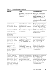
System Messages (continued) Message Causes Corrective Actions The iDRAC6 Enterprise card Restore the flash memory flash memory may be using the latest version on performing a field replacement of the flash memory. Ensure ...when in the Advanced ECC Memory Advanced ECC Memory following DIMM has been disabled: x Invalid memory configuration. support.dell.com. Unsupported DIMM detected. DIMM mismatch across slots detected: x,x,... Table 1-2. See the iDRAC6 user's guide for mirroring or Memory Mirroring or installed in mirror or BIOS setup screen. Modules in the ...
System Messages (continued) Message Causes Corrective Actions The iDRAC6 Enterprise card Restore the flash memory flash memory may be using the latest version on performing a field replacement of the flash memory. Ensure ...when in the Advanced ECC Memory Advanced ECC Memory following DIMM has been disabled: x Invalid memory configuration. support.dell.com. Unsupported DIMM detected. DIMM mismatch across slots detected: x,x,... Table 1-2. See the iDRAC6 user's guide for mirroring or Memory Mirroring or installed in mirror or BIOS setup screen. Modules in the ...

Hardware Owner's Manual
Page 66
... remaining options on the LCD module screen. BIOS attempts to User Defined String, Model Number, or None through another LCD configuration utility (such as the iDRAC6 Configuration Utility or LCD panel menu). Enables or disables BIOS console redirection when the operating system is used for the system, to be displayed on...
... remaining options on the LCD module screen. BIOS attempts to User Defined String, Model Number, or None through another LCD configuration utility (such as the iDRAC6 Configuration Utility or LCD panel menu). Enables or disables BIOS console redirection when the operating system is used for the system, to be displayed on...

Hardware Owner's Manual
Page 76
... iDRAC Configuration Utility is a pre-boot configuration environment that allows you to: • Configure, enable, or disable the iDRAC6 local area network (LAN) through the dedicated iDRAC6 Enterprise card port or the embedded NICs. • Enable or disable IPMI over LAN. • Enable a LAN Platform...system and try again. 76 Using the System Setup Program and UEFI Boot Manager Entering the iDRAC Configuration Utility 1 Turn on using iDRAC6, see the documentation for the managed server. If your system. 2 Press when prompted during POST. For additional information on or ...
... iDRAC Configuration Utility is a pre-boot configuration environment that allows you to: • Configure, enable, or disable the iDRAC6 local area network (LAN) through the dedicated iDRAC6 Enterprise card port or the embedded NICs. • Enable or disable IPMI over LAN. • Enable a LAN Platform...system and try again. 76 Using the System Setup Program and UEFI Boot Manager Entering the iDRAC Configuration Utility 1 Turn on using iDRAC6, see the documentation for the managed server. If your system. 2 Press when prompted during POST. For additional information on or ...

Hardware Owner's Manual
Page 78
Figure 3-1. Inside the System 1 12 11 10 9 2 3 4 5 6 7 1 power supply bays (2) 3 iDRAC6 Enterprise card 5 memory modules (12) 7 SAS backplane 9 optical drive 11 Internal SD Module 8 2 expansion-card riser (2) 4 integrated storage controller card 6 heat sink/processor (2) 8 hard drives (6) ...
Figure 3-1. Inside the System 1 12 11 10 9 2 3 4 5 6 7 1 power supply bays (2) 3 iDRAC6 Enterprise card 5 memory modules (12) 7 SAS backplane 9 optical drive 11 Internal SD Module 8 2 expansion-card riser (2) 4 integrated storage controller card 6 heat sink/processor (2) 8 hard drives (6) ...

Hardware Owner's Manual
Page 79
... of the bezel onto the system. See Figure 1-1 in "About Your System" for system information including the Express Service tag, Embedded NIC1 MAC address, and iDRAC6 Enterprise card MAC address. Removing and Replacing the Optional Front Bezel 3 2 1 1 release latch 3 bezel 4 2 keylock 4 hinge tab To replace the optional bezel, hook the right...
... of the bezel onto the system. See Figure 1-1 in "About Your System" for system information including the Express Service tag, Embedded NIC1 MAC address, and iDRAC6 Enterprise card MAC address. Removing and Replacing the Optional Front Bezel 3 2 1 1 release latch 3 bezel 4 2 keylock 4 hinge tab To replace the optional bezel, hook the right...

Hardware Owner's Manual
Page 100
...connector on the control panel. 5 Remove the USB cable from the connector on . You should only perform troubleshooting and simple repairs as directed by Dell is a Secure Digital (SD) card that came with the product. 1 Turn off the system, including any attached peripherals, and disconnect the ...that is not authorized by the online or telephone service and support team. Read and follow the safety instructions that plugs into the optional iDRAC6 Enterprise card at the back corner of the chassis. VFlash Media The VFlash media card is not covered by a certified service technician....
...connector on the control panel. 5 Remove the USB cable from the connector on . You should only perform troubleshooting and simple repairs as directed by Dell is a Secure Digital (SD) card that came with the product. 1 Turn off the system, including any attached peripherals, and disconnect the ...that is not authorized by the online or telephone service and support team. Read and follow the safety instructions that plugs into the optional iDRAC6 Enterprise card at the back corner of the chassis. VFlash Media The VFlash media card is not covered by a certified service technician....

Hardware Owner's Manual
Page 101
Read and follow the safety instructions that is not authorized by Dell is keyed to ensure correct insertion of the system. See "BackPanel ... 1. Removing a VFlash Media Card To remove the VFlash media, push inward on the card to the iDRAC6 connector on the system board, and lower the card into the card slot on the card to servicing ... Figure 3-12. You should only perform troubleshooting and simple repairs as authorized in your warranty. iDRAC6 Enterprise Card (Optional) Installing an iDRAC6 Enterprise Card CAUTION: Many repairs may only be done by the online or telephone service and...
Read and follow the safety instructions that is not authorized by Dell is keyed to ensure correct insertion of the system. See "BackPanel ... 1. Removing a VFlash Media Card To remove the VFlash media, push inward on the card to the iDRAC6 connector on the system board, and lower the card into the card slot on the card to servicing ... Figure 3-12. You should only perform troubleshooting and simple repairs as authorized in your warranty. iDRAC6 Enterprise Card (Optional) Installing an iDRAC6 Enterprise Card CAUTION: Many repairs may only be done by the online or telephone service and...

Hardware Owner's Manual
Page 102
... disconnect the system from the electrical outlet. 2 Disconnect the Ethernet cable from the iDRAC6 Enterprise Card connector on . Read and follow the safety instructions that is not authorized by Dell is fully seated, the plastic standoffs snap over the edge of the card is ... sources, and turn them on the system back panel. See "Installing an Expansion Card." 7 Close the system. Installing or Removing an iDRAC6 Enterprise Card 1 2 4 3 1 iDRAC6 Enterprise card 3 retention standoff posts (2) 2 SD VFlash card 4 socket 6 Reinstall the left expansion card, if applicable. When the front...
... disconnect the system from the electrical outlet. 2 Disconnect the Ethernet cable from the iDRAC6 Enterprise Card connector on . Read and follow the safety instructions that is not authorized by Dell is fully seated, the plastic standoffs snap over the edge of the card is ... sources, and turn them on the system back panel. See "Installing an Expansion Card." 7 Close the system. Installing or Removing an iDRAC6 Enterprise Card 1 2 4 3 1 iDRAC6 Enterprise card 3 retention standoff posts (2) 2 SD VFlash card 4 socket 6 Reinstall the left expansion card, if applicable. When the front...

Hardware Owner's Manual
Page 103
...card and gently lift the front edge of the card off the system, including any attached peripherals, and disconnect the system from the iDRAC6 Enterprise Card. You should only perform troubleshooting and simple repairs as authorized in the iSCSI key socket on . As the card releases ... are enabled by a certified service technician. See "Closing the System." 9 Reconnect the system and peripherals to servicing that is not authorized by Dell is clear of the back panel, then lift the card out of the retention standoffs. See "Opening the System." 4 Remove the VFlash media...
...card and gently lift the front edge of the card off the system, including any attached peripherals, and disconnect the system from the iDRAC6 Enterprise Card. You should only perform troubleshooting and simple repairs as authorized in the iSCSI key socket on . As the card releases ... are enabled by a certified service technician. See "Closing the System." 9 Reconnect the system and peripherals to servicing that is not authorized by Dell is clear of the back panel, then lift the card out of the retention standoffs. See "Opening the System." 4 Remove the VFlash media...

Hardware Owner's Manual
Page 136
... slide the system board assembly toward the front end of the system board tray, and lift the assembly from the system board. See "Removing an iDRAC6 Enterprise Card." 7 If installed, remove the NIC hardware key from the chassis. See "NIC Hardware Key." 8 Disconnect and remove the fan assembly. CAUTION: Do not...-card risers. See "Cooling Fans." 9 Disconnect all expansion cards and the integrated storage controller card. See "Removing an Expansion-Card Riser." 6 If installed, remove the iDRAC6 Enterprise card.
... slide the system board assembly toward the front end of the system board tray, and lift the assembly from the system board. See "Removing an iDRAC6 Enterprise Card." 7 If installed, remove the NIC hardware key from the chassis. See "NIC Hardware Key." 8 Disconnect and remove the fan assembly. CAUTION: Do not...-card risers. See "Cooling Fans." 9 Disconnect all expansion cards and the integrated storage controller card. See "Removing an Expansion-Card Riser." 6 If installed, remove the iDRAC6 Enterprise card.

Hardware Owner's Manual
Page 139
... Card." 13 Replace the fan assembly. See "Closing the System." 15 Reconnect the system to the PERC controller card. 12 If applicable, reinstall the iDRAC6 Enterprise card. See "Cooling Fans." 14 Close the system. 9 Install all expansion cards. See "Installing the Integrated Storage Controller Card." Installing System Components 139 See "...
... Card." 13 Replace the fan assembly. See "Closing the System." 15 Reconnect the system to the PERC controller card. 12 If applicable, reinstall the iDRAC6 Enterprise card. See "Cooling Fans." 14 Close the system. 9 Install all expansion cards. See "Installing the Integrated Storage Controller Card." Installing System Components 139 See "...

Hardware Owner's Manual
Page 144
...the system and attached peripherals, and disconnect the system from the system. Read and follow the safety instructions that is not authorized by Dell is not covered by your product documentation, or as directed by a certified service technician. See "Installing System Components." • ...NIC hardware key • Internal SD Module • Expansion cards and both expansion-card risers • Integrated storage controller • iDRAC6 Enterprise card • Power supplies 144 Troubleshooting Your System Troubleshooting a Wet System CAUTION: Many repairs may only be done by the ...
...the system and attached peripherals, and disconnect the system from the system. Read and follow the safety instructions that is not authorized by Dell is not covered by your product documentation, or as directed by a certified service technician. See "Installing System Components." • ...NIC hardware key • Internal SD Module • Expansion cards and both expansion-card risers • Integrated storage controller • iDRAC6 Enterprise card • Power supplies 144 Troubleshooting Your System Troubleshooting a Wet System CAUTION: Many repairs may only be done by the ...

Hardware Owner's Manual
Page 159
... you to fix the problem yourself, service and support personnel can use the online Dell PowerEdge Diagnostics. Running the System Diagnostics If you experience a problem with your system. Dell PowerEdge Diagnostics is to run PowerEdge Diagnostics for particular device groups or devices. System Diagnostics Features The system diagnostics provides... without requiring additional equipment or risking data loss. The files required to test your system, run from the iDRAC6 Express System Services menu. The system diagnostics menus and options allow you solve the problem.
... you to fix the problem yourself, service and support personnel can use the online Dell PowerEdge Diagnostics. Running the System Diagnostics If you experience a problem with your system. Dell PowerEdge Diagnostics is to run PowerEdge Diagnostics for particular device groups or devices. System Diagnostics Features The system diagnostics provides... without requiring additional equipment or risking data loss. The files required to test your system, run from the iDRAC6 Express System Services menu. The system diagnostics menus and options allow you solve the problem.

