Dell PowerEdge 4300 Systems Service Manual
Page 3
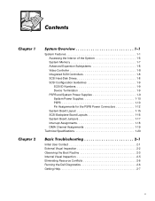
... Termination 1-9 PSPB and System Power Supplies 1-9 System Power Supplies 1-10 PSPB 1-10 Pin Assignments for the PSPB Power Connectors 1-12 System Board Layout... 1-15 SCSI Backplane Board Layouts 1-16 System Board Jumpers 1-17 Interrupt Assignments 1-18 DMA Channel Assignments 1-19 Technical Specifications 1-20 Initial User Contact 2-1 External Visual Inspection 2-2 Observing the Boot Routine 2-3 Internal Visual Inspection 2-5 Eliminating Resource Conflicts 2-6 Running the Dell...
... Termination 1-9 PSPB and System Power Supplies 1-9 System Power Supplies 1-10 PSPB 1-10 Pin Assignments for the PSPB Power Connectors 1-12 System Board Layout... 1-15 SCSI Backplane Board Layouts 1-16 System Board Jumpers 1-17 Interrupt Assignments 1-18 DMA Channel Assignments 1-19 Technical Specifications 1-20 Initial User Contact 2-1 External Visual Inspection 2-2 Observing the Boot Routine 2-3 Internal Visual Inspection 2-5 Eliminating Resource Conflicts 2-6 Running the Dell...
Dell PowerEdge 4300 Systems Service Manual
Page 20
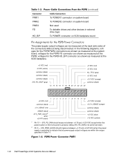
... system board Not used To diskette drives and other devices in Table 1-1. 1-12 Dell PowerEdge 4300 Systems Service Manual SYS_PS_ON# should measure between +4.75 and +5.25 VDC except when the power button on SCSI backplane board The power-supply output voltages can be measured at the SCSI backplane. +5 VDC (red) -5 ...- voltages for the PSPB HD_B/P connector are within the ranges specified in external drive bays To POWER connector on the front panel is operating to its active-low state. 2 Pin 5 - voltages for the PSPB FD connector are shown as measured at the system board; In...
... system board Not used To diskette drives and other devices in Table 1-1. 1-12 Dell PowerEdge 4300 Systems Service Manual SYS_PS_ON# should measure between +4.75 and +5.25 VDC except when the power button on SCSI backplane board The power-supply output voltages can be measured at the SCSI backplane. +5 VDC (red) -5 ...- voltages for the PSPB HD_B/P connector are within the ranges specified in external drive bays To POWER connector on the front panel is operating to its active-low state. 2 Pin 5 - voltages for the PSPB FD connector are shown as measured at the system board; In...
Dell PowerEdge 4300 System Board Upgrade Installation
Page 4
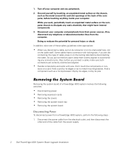
...connector pins. Also, disconnect any static electricity that might harm internal components. 3. In addition, take note of the computer, before touching anything inside your computer and peripherals from a PowerEdge 4300 system, perform the following activities: ‡ Disconnecting power &#...aligned to dissipate any telephone or telecommunication lines from the power supply. 2 Dell PowerEdge 4300 System Board Upgrade Installation if you connect a cable, make sure both connectors are disconnecting this type of a PowerEdge 4300 system involves the following steps : 1. Don’t ...
...connector pins. Also, disconnect any static electricity that might harm internal components. 3. In addition, take note of the computer, before touching anything inside your computer and peripherals from a PowerEdge 4300 system, perform the following activities: ‡ Disconnecting power &#...aligned to dissipate any telephone or telecommunication lines from the power supply. 2 Dell PowerEdge 4300 System Board Upgrade Installation if you connect a cable, make sure both connectors are disconnecting this type of a PowerEdge 4300 system involves the following steps : 1. Don’t ...
Dell PowerEdge 4300 Systems Installation and Troubleshooting Guide
Page 145
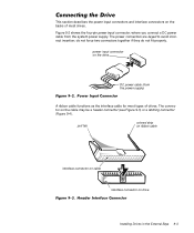
... on the drive DC power cable (from the system power supply. The power connectors are keyed to avoid incorrect insertion; pull tab colored strip on ribbon cable interface connector on cable interface connector on the cable may ... connector on drive Installing Drives in the External Bays 9-3 This section describes the power input connectors and interface connectors on the backs of most types of drives. Figure 9-2 shows the four-pin power input connector, where you connect a DC power cable from the power supply) A ribbon cable functions as the interface cable for most drives.
... on the drive DC power cable (from the system power supply. The power connectors are keyed to avoid incorrect insertion; pull tab colored strip on ribbon cable interface connector on cable interface connector on the cable may ... connector on drive Installing Drives in the External Bays 9-3 This section describes the power input connectors and interface connectors on the backs of most types of drives. Figure 9-2 shows the four-pin power input connector, where you connect a DC power cable from the power supply) A ribbon cable functions as the interface cable for most drives.
Dell PowerEdge 4300 Systems Installation and Troubleshooting Guide
Page 146
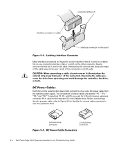
...Dell PowerEdge 4300 Systems Installation and Troubleshooting Guide Before connecting a drive to a power cable, refer to Figure 9-5 to identify the correct cable connector to use for 5.25-inch devices, whereas connector P6 is , a notch or a raised tab on one edge of the cable) goes to a four-wire DC power cable from the system power supply. that the pin...-1 wire in the external drive bays must connect to the pin-1 ends of the connectors on both ends. The connectors on the other...
...Dell PowerEdge 4300 Systems Installation and Troubleshooting Guide Before connecting a drive to a power cable, refer to Figure 9-5 to identify the correct cable connector to use for 5.25-inch devices, whereas connector P6 is , a notch or a raised tab on one edge of the cable) goes to a four-wire DC power cable from the system power supply. that the pin...-1 wire in the external drive bays must connect to the pin-1 ends of the connectors on both ends. The connectors on the other...


