Dell PowerEdge Systems Microprocessor Upgrade Guide
Page 10
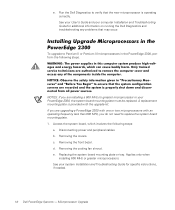
...to Pentium II or Pentium III microprocessors in your computer Installation and Troubleshooting Guide for specific instructions, if needed. 1-6 Dell PowerEdge Systems - A replacement mounting plate is operating correctly. Disconnecting power and peripheral cables. Removing the front bezel. Applies...board mounting plate or tray. c. Removing the cooling fan shroud. Microprocessor Upgrade Removing the covers. d. See your system Installation and Troubleshooting Guide for additional information on running the Dell Diagnostics and troubleshooting any problems that the new microprocessor...
...to Pentium II or Pentium III microprocessors in your computer Installation and Troubleshooting Guide for specific instructions, if needed. 1-6 Dell PowerEdge Systems - A replacement mounting plate is operating correctly. Disconnecting power and peripheral cables. Removing the front bezel. Applies...board mounting plate or tray. c. Removing the cooling fan shroud. Microprocessor Upgrade Removing the covers. d. See your system Installation and Troubleshooting Guide for additional information on running the Dell Diagnostics and troubleshooting any problems that the new microprocessor...
Dell PowerEdge Systems Microprocessor Upgrade Guide
Page 15
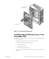
b. c. Removing the front bezel. Microprocessor Upgrade 1-11 inner card-guide brackets (6) thumbscrew To upgrade to Pentium II or Pentium III microprocessors in the PowerEdge 4350, perform the following steps: a. See your system Installation and Troubleshooting Guide for specific instructions, if needed. Disconnecting power and peripheral cables. Removing the covers. Removing the cooling fan shroud. support.dell.com Dell PowerEdge Systems - Access the system board, which involves the following steps: 1. d.
b. c. Removing the front bezel. Microprocessor Upgrade 1-11 inner card-guide brackets (6) thumbscrew To upgrade to Pentium II or Pentium III microprocessors in the PowerEdge 4350, perform the following steps: a. See your system Installation and Troubleshooting Guide for specific instructions, if needed. Disconnecting power and peripheral cables. Removing the covers. Removing the cooling fan shroud. support.dell.com Dell PowerEdge Systems - Access the system board, which involves the following steps: 1. d.
Dell PowerEdge Systems Microprocessor Upgrade Guide
Page 19
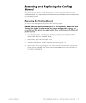
... remove the cooling shroud, perform the following steps. 1. Unscrew and remove the two retention pins (see Figure 1-7). 4. support.dell.com Dell PowerEdge Systems - You may need to remove this shroud to access certain components on the system back panel. Remove the right-side computer... system is used to the microproces- Turn off the system, including any attached peripherals, and disconnect the power cable from the cooling fan on the system board. sor(s) until the opposite end of the shroud closest to improve airflow over the microprocessors. Microprocessor Upgrade 1-15...
... remove the cooling shroud, perform the following steps. 1. Unscrew and remove the two retention pins (see Figure 1-7). 4. support.dell.com Dell PowerEdge Systems - You may need to remove this shroud to access certain components on the system back panel. Remove the right-side computer... system is used to the microproces- Turn off the system, including any attached peripherals, and disconnect the power cable from the cooling fan on the system board. sor(s) until the opposite end of the shroud closest to improve airflow over the microprocessors. Microprocessor Upgrade 1-15...

Dell PowerEdge Systems Microprocessor Upgrade Guide
Page 20
Secure the shroud by reinstalling the two retention pins. 1-16 Dell PowerEdge Systems - Microprocessor Upgrade thumbscrew retention pins (2) To replace the cooling shroud, perform the following steps: 1. Lower the other end of the shroud into place over the top of the cooling shroud over the microprocessor(s). 3. Hook the upper edge of the large opening on the end of the cooling fan on the system back panel. 2.
Secure the shroud by reinstalling the two retention pins. 1-16 Dell PowerEdge Systems - Microprocessor Upgrade thumbscrew retention pins (2) To replace the cooling shroud, perform the following steps: 1. Lower the other end of the shroud into place over the top of the cooling shroud over the microprocessor(s). 3. Hook the upper edge of the large opening on the end of the cooling fan on the system back panel. 2.

Dell PowerEdge Systems Microprocessor Upgrade Guide
Page 22
...a cooling shroud came with the square opening over the microprocessors, as you must install the cooling shroud provided in Figure 1-9. 2. head fan and the top of the shroud's other end resting over the bulk- Microprocessor Upgrade Carefully position the shroud into place with your microprocessor... upgrade kit and your system is a PowerEdge 1300 or PowerEdge 2300, you lower the shroud on the microprocessor's heat sink and allow it to compress the latch as shown in the ...
...a cooling shroud came with the square opening over the microprocessors, as you must install the cooling shroud provided in Figure 1-9. 2. head fan and the top of the shroud's other end resting over the bulk- Microprocessor Upgrade Carefully position the shroud into place with your microprocessor... upgrade kit and your system is a PowerEdge 1300 or PowerEdge 2300, you lower the shroud on the microprocessor's heat sink and allow it to compress the latch as shown in the ...
Dell PowerEdge 4300 Systems User's Guide
Page 13
... Screens 4-2 Using the System Setup Program 4-3 System Setup Options 4-5 Time 4-5 Date 4-5 Diskette Drive A and Diskette Drive B 4-5 Reserved Memory 4-5 CPU Speed 4-6 Num Lock 4-6 Processor 1 and Processor 2 4-6 Fan Speed 4-6 System Alert 4-6 Keyboard Errors 4-7 Boot Sequence 4-7 Diskette First 4-7 Hard Disk Only 4-7 Scan Sequence 4-7 System Password 4-8 Password Status 4-8 Setup Password 4-8 Mouse 4-9 Serial Port 1 and Serial...
... Screens 4-2 Using the System Setup Program 4-3 System Setup Options 4-5 Time 4-5 Date 4-5 Diskette Drive A and Diskette Drive B 4-5 Reserved Memory 4-5 CPU Speed 4-6 Num Lock 4-6 Processor 1 and Processor 2 4-6 Fan Speed 4-6 System Alert 4-6 Keyboard Errors 4-7 Boot Sequence 4-7 Diskette First 4-7 Hard Disk Only 4-7 Scan Sequence 4-7 System Password 4-8 Password Status 4-8 Setup Password 4-8 Mouse 4-9 Serial Port 1 and Serial...
Dell PowerEdge 4300 Systems User's Guide
Page 20
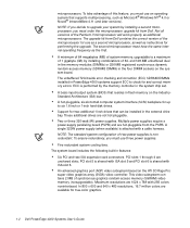
...320W power supply (when available) is shared with a cable harness. The upgrade kit from Dell. A hot-pluggable, six-slot small computer system interface (SCSI) backplane for true-color graphics. 1-2 Dell PowerEdge 4300 Systems User's Guide PCI slot 5 is shared with ISA slot 5 and PCI slot ...6 is attached with ISA slot 6. A minimum of 64 megabytes (MB) of the microprocessor for use three power supplies. ECC is nonredundant. Five redundant system cooling fans. In 800 ...
...320W power supply (when available) is shared with a cable harness. The upgrade kit from Dell. A hot-pluggable, six-slot small computer system interface (SCSI) backplane for true-color graphics. 1-2 Dell PowerEdge 4300 Systems User's Guide PCI slot 5 is shared with ISA slot 5 and PCI slot ...6 is attached with ISA slot 6. A minimum of 64 megabytes (MB) of the microprocessor for use three power supplies. ECC is nonredundant. Five redundant system cooling fans. In 800 ...
Dell PowerEdge 4300 Systems User's Guide
Page 21
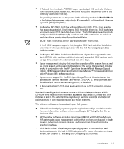
...An Adaptec AIC-7860 Ultra/Narrow SCSI-3 host adapter that monitors operation of the system fans as well as tape drive units) in the external hard-disk drive bays. A Personal...in-depth views of networked systems, devices, and connections through an intuitive graphical interface. Standard PowerEdge 4300 systems include a 3.5-inch diskette drive and a SCSI CD-ROM drive installed in the externally...is installed. The parallel port can be set to the built-in conjunction with the Dell PowerEdge Expandable RAID Controller. For more information on these drivers, see Chapter 3, "Installing and...
...An Adaptec AIC-7860 Ultra/Narrow SCSI-3 host adapter that monitors operation of the system fans as well as tape drive units) in the external hard-disk drive bays. A Personal...in-depth views of networked systems, devices, and connections through an intuitive graphical interface. Standard PowerEdge 4300 systems include a 3.5-inch diskette drive and a SCSI CD-ROM drive installed in the externally...is installed. The parallel port can be set to the built-in conjunction with the Dell PowerEdge Expandable RAID Controller. For more information on these drivers, see Chapter 3, "Installing and...

Dell PowerEdge 4300 Systems User's Guide
Page 22
...door on and the system is recessed into the system's front panel to prevent you from the hard-disk drive. 1-4 Dell PowerEdge 4300 Systems User's Guide The System Setup program for quickly viewing and changing the system configuration information for evaluating your system's components ...front panel (see Chapter 5, "Using the Resource Configuration Utility." For more information, see Figure 1-1): The green fan/temperature status indicator blinks amber when a fan failure is detected or temperature is being transferred to the system board from the power supply. The green power ...
...door on and the system is recessed into the system's front panel to prevent you from the hard-disk drive. 1-4 Dell PowerEdge 4300 Systems User's Guide The System Setup program for quickly viewing and changing the system configuration information for evaluating your system's components ...front panel (see Chapter 5, "Using the Resource Configuration Utility." For more information, see Figure 1-1): The green fan/temperature status indicator blinks amber when a fan failure is detected or temperature is being transferred to the system board from the power supply. The green power ...

Dell PowerEdge 4300 Systems User's Guide
Page 23
diskette drive CD-ROM drive power indicator power button power-supply status indicator fan/temperature status indicator keylock Introduction 1-5 The amber hard-disk drive failure indicator blinks if a hard-disk drive failure is detected.
diskette drive CD-ROM drive power indicator power button power-supply status indicator fan/temperature status indicator keylock Introduction 1-5 The amber hard-disk drive failure indicator blinks if a hard-disk drive failure is detected.
Dell PowerEdge 4300 Systems User's Guide
Page 70
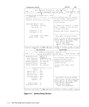
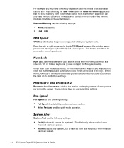
...Fan Speed: Full Speed System Alert: Fault Pentium®II Processor 400 MHz Level 2 Cache: 512 KB Integrated System Memory: 64 MB ECC SDRAM Video Memory: 2MB SGRAM Service Tag: XXXXX Asset Tag: XXXXXXXXXX Tab,Shift-Tab change fields , key functions change values Alt-P next Esc exit Alt-B reboot 4-4 Dell PowerEdge 4300..., Num Lock: On enter a number or use the left- configuration options title box help Dell Computer Corporation (www.dell.com) Page 1 of 2 System PowerEdge® 4300/400 Setup BIOS Version: XXX Keyboard Errors: Boot Sequence: Scan Sequence: System Password: Password ...
...Fan Speed: Full Speed System Alert: Fault Pentium®II Processor 400 MHz Level 2 Cache: 512 KB Integrated System Memory: 64 MB ECC SDRAM Video Memory: 2MB SGRAM Service Tag: XXXXX Asset Tag: XXXXXXXXXX Tab,Shift-Tab change fields , key functions change values Alt-P next Esc exit Alt-B reboot 4-4 Dell PowerEdge 4300..., Num Lock: On enter a number or use the left- configuration options title box help Dell Computer Corporation (www.dell.com) Page 1 of 2 System PowerEdge® 4300/400 Setup BIOS Version: XXX Keyboard Errors: Boot Sequence: Scan Sequence: System Password: Password ...
Dell PowerEdge 4300 Systems User's Guide
Page 72
... memory below the 15-MB address comes from the dual in the system. Processor 1 and Processor 2 display the version or stepping number of the keys. Fan Speed has the following settings: Fault (the default) causes the system LED to be used under normal operations. When Num Lock mode is activated, the...). When Num Lock mode is turned off, these keys provide cursor-control functions according to flash as soon as a noncritical error threshold has been passed. 4-6 Dell PowerEdge 4300 Systems User's Guide
... memory below the 15-MB address comes from the dual in the system. Processor 1 and Processor 2 display the version or stepping number of the keys. Fan Speed has the following settings: Fault (the default) causes the system LED to be used under normal operations. When Num Lock mode is activated, the...). When Num Lock mode is turned off, these keys provide cursor-control functions according to flash as soon as a noncritical error threshold has been passed. 4-6 Dell PowerEdge 4300 Systems User's Guide

Dell PowerEdge 4300 Systems User's Guide
Page 112
...program included in the system's internal temperature and interferes with these areas can often be reversed with the operation of various system components. C-2 Dell PowerEdge 4300 Systems User's Guide Even losses such as the Norton Utilities, Mace Utilities, or PC-Tools Deluxe, the data stored in the power supply... cools the power supply and system by Brady. An exhaust fan in these utilities. If the system is written to corruption or erasure of the hard-disk drive's master boot record (MBR), MS-DOS...
...program included in the system's internal temperature and interferes with these areas can often be reversed with the operation of various system components. C-2 Dell PowerEdge 4300 Systems User's Guide Even losses such as the Norton Utilities, Mace Utilities, or PC-Tools Deluxe, the data stored in the power supply... cools the power supply and system by Brady. An exhaust fan in these utilities. If the system is written to corruption or erasure of the hard-disk drive's master boot record (MBR), MS-DOS...

Dell PowerEdge 4300 Systems User's Guide
Page 114
...operating at regular intervals to a heat source of temperature on system performance, follow these guidelines: Ensure that accumulate on the disk platters. C-4 Dell PowerEdge 4300 Systems User's Guide If the kit does not contain instructions, insert one of your diskette drives by using a commercially available diskette-drive head...loose in their sockets and can cause a system to ensure that all slots and openings on the system remain unobstructed, especially the fan vent on top of the system. To minimize the negative effects of any buildup of devices. Do not place it will be ...
...operating at regular intervals to a heat source of temperature on system performance, follow these guidelines: Ensure that accumulate on the disk platters. C-4 Dell PowerEdge 4300 Systems User's Guide If the kit does not contain instructions, insert one of your diskette drives by using a commercially available diskette-drive head...loose in their sockets and can cause a system to ensure that all slots and openings on the system remain unobstructed, especially the fan vent on top of the system. To minimize the negative effects of any buildup of devices. Do not place it will be ...

Dell PowerEdge 4300 Systems User's Guide
Page 156
... system, C-3 EZ-SCSI creating diskette, 2-6 Fan Speed option, 4-6 features system, 1-1 front panel controls and indicators, 1-4 illustrated, 1-5, 1-6 getting help, 1-7 grounding strap, C-3 hard disk. See EMI electrostatic discharge. See drives; See ESD EMI, C-6 environmental specifications, A-3 error correction code. SCSI devices Hard Disk Only option, 4-7 2 Dell PowerEdge 4300 Systems User's Guide Dell Server Assistant CD about, 2-2, 2-6 booting system...
... system, C-3 EZ-SCSI creating diskette, 2-6 Fan Speed option, 4-6 features system, 1-1 front panel controls and indicators, 1-4 illustrated, 1-5, 1-6 getting help, 1-7 grounding strap, C-3 hard disk. See EMI electrostatic discharge. See drives; See ESD EMI, C-6 environmental specifications, A-3 error correction code. SCSI devices Hard Disk Only option, 4-7 2 Dell PowerEdge 4300 Systems User's Guide Dell Server Assistant CD about, 2-2, 2-6 booting system...

Dell PowerEdge 4300 Systems Service Manual
Page 4
POST Beep Codes 3-1 System Messages 3-5 Alert Messages From Dell OpenManage HIP 3-13 SCSI Hard-Disk Drive Indicator Codes 3-17 Recommended Tools 4-1 Precautionary Measures 4-2 Computer Cover 4-3 Front Bezel 4-4 Control Panel Assembly 4-5 Drives 4-6 ...System Power Supply 4-16 System Power Supply and PSPB Upgrade 4-17 Power-Supply Paralleling Board 4-21 System Cooling Fans 4-22 Three-Fan Assembly 4-23 Fan Power-Cable Bundle 4-24 Drive Fan 4-24 System Board Fans 4-25 System Board Components 4-26 Expansion Cards 4-27 Interior Support Panel 4-29 DIMMs 4-30 SEC Cartridge and ...
POST Beep Codes 3-1 System Messages 3-5 Alert Messages From Dell OpenManage HIP 3-13 SCSI Hard-Disk Drive Indicator Codes 3-17 Recommended Tools 4-1 Precautionary Measures 4-2 Computer Cover 4-3 Front Bezel 4-4 Control Panel Assembly 4-5 Drives 4-6 ...System Power Supply 4-16 System Power Supply and PSPB Upgrade 4-17 Power-Supply Paralleling Board 4-21 System Cooling Fans 4-22 Three-Fan Assembly 4-23 Fan Power-Cable Bundle 4-24 Drive Fan 4-24 System Board Fans 4-25 System Board Components 4-26 Expansion Cards 4-27 Interior Support Panel 4-29 DIMMs 4-30 SEC Cartridge and ...

Dell PowerEdge 4300 Systems Service Manual
Page 5
... 1-10. Figure 3-1. Figure 4-2. Figure 4-9. Figure 4-14. Figure 4-19. Multiple Power Supplies . . . 4-20 Power-Supply Paralleling Board Removal 4-21 System Cooling Fans 4-22 Three-Fan Assembly Removal 4-23 Drive Fan Removal 4-24 System-Board Fan Removal 4-25 vii Figure 1-3. Figure 1-6. Figure 1-7. Figure 4-7. Figure 4-12. Figure 4-18. Figure 1-13. Figure 4-17. System Setup Screens A-2 Figure 1-1. Figure...
... 1-10. Figure 3-1. Figure 4-2. Figure 4-9. Figure 4-14. Figure 4-19. Multiple Power Supplies . . . 4-20 Power-Supply Paralleling Board Removal 4-21 System Cooling Fans 4-22 Three-Fan Assembly Removal 4-23 Drive Fan Removal 4-24 System-Board Fan Removal 4-25 vii Figure 1-3. Figure 1-6. Figure 1-7. Figure 4-7. Figure 4-12. Figure 4-18. Figure 1-13. Figure 4-17. System Setup Screens A-2 Figure 1-1. Figure...
Dell PowerEdge 4300 Systems Service Manual
Page 10
... internal SCSI hard-disk drives via a SCSI backplane board and special SCSI hard-disk drive carriers. Five redundant system cooling fans. Six 32-bit PCI connectors and two shared 8-bit or 16-bit ISA connectors. An integrated Adaptec AIC-7860 Ultra/Narrow...management circuitry works in the externally accessible front bay. System board support for the Dell OpenManage Remote Assistant when the optional Dell Remote Assistant Card version 2 (DRAC 2), which is installed. 1-2 Dell PowerEdge 4300 Systems Service Manual Drive failure, online, and activity indicators visible on individual hard-disk...
... internal SCSI hard-disk drives via a SCSI backplane board and special SCSI hard-disk drive carriers. Five redundant system cooling fans. Six 32-bit PCI connectors and two shared 8-bit or 16-bit ISA connectors. An integrated Adaptec AIC-7860 Ultra/Narrow...management circuitry works in the externally accessible front bay. System board support for the Dell OpenManage Remote Assistant when the optional Dell Remote Assistant Card version 2 (DRAC 2), which is installed. 1-2 Dell PowerEdge 4300 Systems Service Manual Drive failure, online, and activity indicators visible on individual hard-disk...
Dell PowerEdge 4300 Systems Service Manual
Page 12
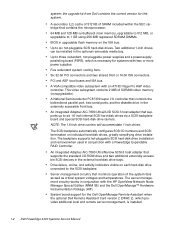
diskette drive CD-ROM drive power-supply status indicator fan/temperature status indicator drive access indicators (3) external SCSI connector port (2) mouse connector keyboard connector server management bus (SMB) connectors (2) serial port 1 connector parallel port connector serial port 2 connector video connector expansion slots (6) power indicator power switch hard-disk drive keylock optional redundant power supply AC power receptacle 1-4 Dell PowerEdge 4300 Systems Service Manual
diskette drive CD-ROM drive power-supply status indicator fan/temperature status indicator drive access indicators (3) external SCSI connector port (2) mouse connector keyboard connector server management bus (SMB) connectors (2) serial port 1 connector parallel port connector serial port 2 connector video connector expansion slots (6) power indicator power switch hard-disk drive keylock optional redundant power supply AC power receptacle 1-4 Dell PowerEdge 4300 Systems Service Manual

Dell PowerEdge 4300 Systems Service Manual
Page 13
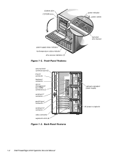
external drive bays (4) hard-disk drive bays (6) SCSI backplane board support panel PCI expansion card hard-disk drive cooling fan assembly microprocessors system board fans tray latch system board System Overview 1-5
external drive bays (4) hard-disk drive bays (6) SCSI backplane board support panel PCI expansion card hard-disk drive cooling fan assembly microprocessors system board fans tray latch system board System Overview 1-5


