
Reference and Installation Guide (.pdf)
Page 3
... safety guidelines: • To help you correctly position your keyboard. • Set the monitor at a comfortable viewing distance (usually 510 to 610 millimeters [20 to 24 inches] from Dell and other sources) to help avoid damaging your computer, be sure the voltage selection switch on the power supply is at your location...
... safety guidelines: • To help you correctly position your keyboard. • Set the monitor at a comfortable viewing distance (usually 510 to 610 millimeters [20 to 24 inches] from Dell and other sources) to help avoid damaging your computer, be sure the voltage selection switch on the power supply is at your location...
Reference and Installation Guide (.pdf)
Page 32
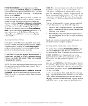
... also be implemented at any level causes EIDE hard-disk drives to switch to lowpower mode after about 20 minutes of a mouse connected to the Personal System/2 (PS/2)compatible mouse port. They remain idle until...System User's Guide.) Saving Monitor Power If you have a DPMS-compliant monitor before you have used the Dell Energy Manager to customize your monitor is minimal). Saving EIDE Hard-Disk Drive Power For most DPMS-compliant ... feature. Otherwise, you next access the hard-disk drive.) 2-8 Dell OptiPlex Gs and Gs+ Low-Profile Systems Reference and Installation Guide
... also be implemented at any level causes EIDE hard-disk drives to switch to lowpower mode after about 20 minutes of a mouse connected to the Personal System/2 (PS/2)compatible mouse port. They remain idle until...System User's Guide.) Saving Monitor Power If you have a DPMS-compliant monitor before you have used the Dell Energy Manager to customize your monitor is minimal). Saving EIDE Hard-Disk Drive Power For most DPMS-compliant ... feature. Otherwise, you next access the hard-disk drive.) 2-8 Dell OptiPlex Gs and Gs+ Low-Profile Systems Reference and Installation Guide
Reference and Installation Guide (.pdf)
Page 33
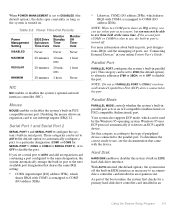
... Periods Power Management Setting EIDE Drive Spindown Time-Outs Monitor Standby TimeOuts Monitor Off TimeOuts DISABLED Never Never Never MAXIMUM 20 minutes 10 min- 1 hour utes REGULAR 20 minutes 20 min- 1 hour utes MINIMUM 20 minutes 1 hour Never NIC NIC enables or disables the system's optional network interface controller (NIC). With AUTO selected (the...
... Periods Power Management Setting EIDE Drive Spindown Time-Outs Monitor Standby TimeOuts Monitor Off TimeOuts DISABLED Never Never Never MAXIMUM 20 minutes 10 min- 1 hour utes REGULAR 20 minutes 20 min- 1 hour utes MINIMUM 20 minutes 1 hour Never NIC NIC enables or disables the system's optional network interface controller (NIC). With AUTO selected (the...

Reference and Installation Guide (.pdf)
Page 97
... table, see the Glossary in the resource box for adding the card as follows: • 4 DMA channels • 7 IRQ lines • 9 memory address blocks • 20 I /O port values can be added. ISA Configuration Utility Messages A-3 To accept these settings to take effect. For the new configuration to take effect, save . The...
... table, see the Glossary in the resource box for adding the card as follows: • 4 DMA channels • 7 IRQ lines • 9 memory address blocks • 20 I /O port values can be added. ISA Configuration Utility Messages A-3 To accept these settings to take effect. For the new configuration to take effect, save . The...

Service Manual (.pdf)
Page 3
... Connectors 1-10 DC Power Distribution 1-11 System Board 1-16 Main Memory 1-16 System Board Jumpers 1-17 DMA Channel Assignments 1-18 Interrupt Assignments 1-19 Technical Specifications 1-20 v
... Connectors 1-10 DC Power Distribution 1-11 System Board 1-16 Main Memory 1-16 System Board Jumpers 1-17 DMA Channel Assignments 1-18 Interrupt Assignments 1-19 Technical Specifications 1-20 v

Service Manual (.pdf)
Page 5
SIMMs 4-16 Video Memory Chips 4-17 Microprocessor/Heat Sink Assembly 4-18 System Battery 4-20 System Board 4-21 Chapter 5 Removing and Replacing Parts in the Midsize System 5-1 Recommended Tools 5-1 Precautionary Measures 5-2 Floor Stand 5-3 Computer Cover 5-4 Eject, Power, and Reset Buttons 5-5... Components 5-14 Expansion Cards 5-15 Expansion-Card Cage 5-15 Expansion Card 5-16 Riser Board 5-17 SIMMs 5-18 Video Memory Chip 5-19 Microprocessor/Heat Sink Assembly 5-20 System Battery 5-22 System Board 5-23 Appendix A System Setup Program A-1 System Setup Screens A-2 Index vii
SIMMs 4-16 Video Memory Chips 4-17 Microprocessor/Heat Sink Assembly 4-18 System Battery 4-20 System Board 4-21 Chapter 5 Removing and Replacing Parts in the Midsize System 5-1 Recommended Tools 5-1 Precautionary Measures 5-2 Floor Stand 5-3 Computer Cover 5-4 Eject, Power, and Reset Buttons 5-5... Components 5-14 Expansion Cards 5-15 Expansion-Card Cage 5-15 Expansion Card 5-16 Riser Board 5-17 SIMMs 5-18 Video Memory Chip 5-19 Microprocessor/Heat Sink Assembly 5-20 System Battery 5-22 System Board 5-23 Appendix A System Setup Program A-1 System Setup Screens A-2 Index vii

Service Manual (.pdf)
Page 6
... 1-7. Eject-, Power, and Reset-Button Removal 4-4 Figure 4-3. Riser Board Removal 4-15 Figure 4-14. Microprocessor and Heat Sink Assembly 4-19 Figure 4-19. System Battery Removal 4-20 Figure 4-20. Internal View of the Low-Profile Computer 1-4 Figure 1-4. DC Power Connectors P2 (Low-Profile Computer) and P7 (Midsize Computer 1-11 Figure 1-10. System Board Jumpers...
... 1-7. Eject-, Power, and Reset-Button Removal 4-4 Figure 4-3. Riser Board Removal 4-15 Figure 4-14. Microprocessor and Heat Sink Assembly 4-19 Figure 4-19. System Battery Removal 4-20 Figure 4-20. Internal View of the Low-Profile Computer 1-4 Figure 1-4. DC Power Connectors P2 (Low-Profile Computer) and P7 (Midsize Computer 1-11 Figure 1-10. System Board Jumpers...

Service Manual (.pdf)
Page 7
Front-Panel Insert Removal 5-6 Figure 5-5. Control Panel Removal 5-7 Figure 5-6. Video-Memory Chip Removal 5-19 Figure 5-20. System Setup Screens A-2 Tables Table 1-1. Table 1-5. Table A-1. SIMM Removal 5-18 Figure 5-18. Microprocessor and Heat ... 5-17 Figure 5-17. DC Voltage Ranges 1-9 System-Board Jumper Descriptions 1-18 DREQ Line Assignments 1-18 Interrupt Assignments 1-19 Technical Specifications 1-20 POST Beep Codes 3-2 System Error Messages 3-5 System Setup Categories A-3 ix Floor Stand Removal 5-3 Figure 5-2. System Board Components 5-14 Figure ...
Front-Panel Insert Removal 5-6 Figure 5-5. Control Panel Removal 5-7 Figure 5-6. Video-Memory Chip Removal 5-19 Figure 5-20. System Setup Screens A-2 Tables Table 1-1. Table 1-5. Table A-1. SIMM Removal 5-18 Figure 5-18. Microprocessor and Heat ... 5-17 Figure 5-17. DC Voltage Ranges 1-9 System-Board Jumper Descriptions 1-18 DREQ Line Assignments 1-18 Interrupt Assignments 1-19 Technical Specifications 1-20 POST Beep Codes 3-2 System Error Messages 3-5 System Setup Categories A-3 ix Floor Stand Removal 5-3 Figure 5-2. System Board Components 5-14 Figure ...

Service Manual (.pdf)
Page 21
...) 22.0 A1 (midsize computer) +12 VDC +11.40 to +12.60 VDC 3.0 A2 (low-profile computer) 6.0 A2 (midsize computer) -12 VDC -10.80 to -13.20 VDC 0.3 A -5 VDC -4.50 to -5.50 VDC 0.3 A +5 VFP3 +4.75 to their corresponding power input connectors on the midsize computer. 2 Withstands surges of 115 VAC at 60...
...) 22.0 A1 (midsize computer) +12 VDC +11.40 to +12.60 VDC 3.0 A2 (low-profile computer) 6.0 A2 (midsize computer) -12 VDC -10.80 to -13.20 VDC 0.3 A -5 VDC -4.50 to -5.50 VDC 0.3 A +5 VFP3 +4.75 to their corresponding power input connectors on the midsize computer. 2 Withstands surges of 115 VAC at 60...

Service Manual (.pdf)
Page 22
DC Power Connectors P2 (Midsize Computer), P3, P4, P5, and P6 (Midsize Computer) 1-10 Dell OptiPlex Gs and Gs+ Systems Service Manual Thermal fan-speed control (TFSC) is pressed, taking PSON# to its active-low state. 2 Pin 5 - Pin Assignments for the DC ...) common (black) +5 VDC (red) common (black) +5 VDC (red) common (black) TFSC 3 (brown) PSON# 1 (grey) +5 VDC (red) 11 12 13 14 15 16 17 18 19 20 P1 1 2 3 4 5 6 7 8 9 10 +5 VDC (red) common (black) common (black) +5 VDC (red) common (black) -12 VDC (blue) common (black) PWRGOOD 2 (orange) +12 VDC (yellow) +5 VFP (purple)...
DC Power Connectors P2 (Midsize Computer), P3, P4, P5, and P6 (Midsize Computer) 1-10 Dell OptiPlex Gs and Gs+ Systems Service Manual Thermal fan-speed control (TFSC) is pressed, taking PSON# to its active-low state. 2 Pin 5 - Pin Assignments for the DC ...) common (black) +5 VDC (red) common (black) +5 VDC (red) common (black) TFSC 3 (brown) PSON# 1 (grey) +5 VDC (red) 11 12 13 14 15 16 17 18 19 20 P1 1 2 3 4 5 6 7 8 9 10 +5 VDC (red) common (black) common (black) +5 VDC (red) common (black) -12 VDC (blue) common (black) PWRGOOD 2 (orange) +12 VDC (yellow) +5 VFP (purple)...

Service Manual (.pdf)
Page 32
... one ISA connector share an expansion-card slot) Midsize computer three (one PCI connector and one PCI connector share an expansion-card slot) NIC NIC (Gs+ systems integrated 3Com network controller attached to the microprocessor System Information System chip set Intel 430FX PCI chip set Data bus width 64 bits Address..., 166, or 200 MHz Internal system clock 66 MHz Internal cache 16 KB Math coprocessor internal to the ISA bus, operating at 10 Mb/sec 1-20 Dell OptiPlex Gs and Gs+ Systems Service Manual ISA: 8.25 MHz PCI expansion-card connectors: Low-profile computer. . . .
... one ISA connector share an expansion-card slot) Midsize computer three (one PCI connector and one PCI connector share an expansion-card slot) NIC NIC (Gs+ systems integrated 3Com network controller attached to the microprocessor System Information System chip set Intel 430FX PCI chip set Data bus width 64 bits Address..., 166, or 200 MHz Internal system clock 66 MHz Internal cache 16 KB Math coprocessor internal to the ISA bus, operating at 10 Mb/sec 1-20 Dell OptiPlex Gs and Gs+ Systems Service Manual ISA: 8.25 MHz PCI expansion-card connectors: Low-profile computer. . . .

Service Manual (.pdf)
Page 35
System Overview 1-23 Above 914.6 m (3000 ft), the maximum operating temperature is for mini tower orientation) and bottom half-sine pulse with a velocity change of 20 inches/sec (50.8 cm/sec) Storage 27-G faired square wave with a velocity change of 200 inches/sec (508 cm/sec) Altitude: Operating 16 to 3048 m* (-...
System Overview 1-23 Above 914.6 m (3000 ft), the maximum operating temperature is for mini tower orientation) and bottom half-sine pulse with a velocity change of 20 inches/sec (50.8 cm/sec) Storage 27-G faired square wave with a velocity change of 200 inches/sec (508 cm/sec) Altitude: Operating 16 to 3048 m* (-...

Service Manual (.pdf)
Page 74
... a printed copy of its socket and snap it is incorrectly installed. Remove the battery. Then restore the system configuration information using the printed copy. 4-20 Dell OptiPlex Gs and Gs+ Systems Service Manual When you replace the system battery, orient the new battery with the same or equivalent type recommended by the manufacturer. System Battery...
... a printed copy of its socket and snap it is incorrectly installed. Remove the battery. Then restore the system configuration information using the printed copy. 4-20 Dell OptiPlex Gs and Gs+ Systems Service Manual When you replace the system battery, orient the new battery with the same or equivalent type recommended by the manufacturer. System Battery...

Service Manual (.pdf)
Page 75
... twist the system board). Carefully lift the system board out of the chassis. 5. Push evenly on the replacement board. System Board screw slots (5) tabs (5) Figure 4-20.
... twist the system board). Carefully lift the system board out of the chassis. 5. Push evenly on the replacement board. System Board screw slots (5) tabs (5) Figure 4-20.

Service Manual (.pdf)
Page 96
... position (see Figure 5-12). 2. Be sure the assembly has had sufficient time to release clip microprocessor securing clip (hooks over tabs on the socket) Figure 5-20. Unlatch and rotate the power supply to the right (see Figure 5-21). 4. Then remove the heat sink from the microprocessor/heat sink assembly. Microprocessor Securing... microprocessor/heat sink assembly can get extremely hot during system operations. Lift the microprocessor chip out of the clip with a small screwdriver to its socket. 5-20 Dell OptiPlex Gs and Gs+ Systems Service Manual
... position (see Figure 5-12). 2. Be sure the assembly has had sufficient time to release clip microprocessor securing clip (hooks over tabs on the socket) Figure 5-20. Unlatch and rotate the power supply to the right (see Figure 5-21). 4. Then remove the heat sink from the microprocessor/heat sink assembly. Microprocessor Securing... microprocessor/heat sink assembly can get extremely hot during system operations. Lift the microprocessor chip out of the clip with a small screwdriver to its socket. 5-20 Dell OptiPlex Gs and Gs+ Systems Service Manual

Service Manual (.pdf)
Page 107
shooting, 2-3 C CD-ROM drive removal, 4-9, 5-10 computer cover removal, 4-3, 5-4 orientation, 1-3 technical specifications, 1-20 connectors on back of low-profile computer, 1-4 on back of midsize computer, 1-5 control panel removal, 4-6, 5-7 cover, removal, 4-3, 5-4 D DC power connectors, 1-10 distribution, low-profile... computer, 1-6 midsize computer, 1-6 external visual inspection, 2-2 Index 1 Index Numbers 3.5-inch diskette-drive assembly removal, 4-8, 5-9 5.25-inch drive assembly removal, 4-9, 5-10 B battery removal, 4-20, 5-22 beep codes, 3-1 boot routine, observing when trouble-
shooting, 2-3 C CD-ROM drive removal, 4-9, 5-10 computer cover removal, 4-3, 5-4 orientation, 1-3 technical specifications, 1-20 connectors on back of low-profile computer, 1-4 on back of midsize computer, 1-5 control panel removal, 4-6, 5-7 cover, removal, 4-3, 5-4 D DC power connectors, 1-10 distribution, low-profile... computer, 1-6 midsize computer, 1-6 external visual inspection, 2-2 Index 1 Index Numbers 3.5-inch diskette-drive assembly removal, 4-8, 5-9 5.25-inch drive assembly removal, 4-9, 5-10 B battery removal, 4-20, 5-22 beep codes, 3-1 boot routine, observing when trouble-

Service Manual (.pdf)
Page 108
... 1-22, A-1 M messages, error, 3-4 microprocessor removal, 4-18, 5-20 securing-clip removal, 4-18, 5-20 N NIC, 1-8 P PCI expansion-card connectors low-profile computer, 1-6 ...midsize computer, 1-6 Plug and Play expansion cards, 1-5 POST beep codes, 3-1 power button removal, 4-4, 5-5 power supply about, 1-9 cables, low-profile computer, 1-12 cables, midsize computer, 1-14 power distribution, low-profile computer, 1-13 power distribution, midsize computer, 1-15 removal, 4-11, 5-13 voltage ranges, 1-9 2 Dell OptiPlex Gs and Gs...
... 1-22, A-1 M messages, error, 3-4 microprocessor removal, 4-18, 5-20 securing-clip removal, 4-18, 5-20 N NIC, 1-8 P PCI expansion-card connectors low-profile computer, 1-6 ...midsize computer, 1-6 Plug and Play expansion cards, 1-5 POST beep codes, 3-1 power button removal, 4-4, 5-5 power supply about, 1-9 cables, low-profile computer, 1-12 cables, midsize computer, 1-14 power distribution, low-profile computer, 1-13 power distribution, midsize computer, 1-15 removal, 4-11, 5-13 voltage ranges, 1-9 2 Dell OptiPlex Gs and Gs...

Service Manual (.pdf)
Page 109
... board removal, 4-15, 5-17 S SIMMs installation, 4-16, 5-18 installation rules, 1-16 removal, 4-16, 5-18 types and sizes, 1-16 specifications, 1-20 subsystems EIDE, 1-7 expansion, 1-5 memory, 1-16 network controller, 1-8 video, 1-7 system battery removal, 4-20, 5-22 system board component locations, 1-16 jumpers, 1-17 removal, 4-21, 5-23 system error messages, 3-4 system features, 1-2 System Setup program, A-1 system...
... board removal, 4-15, 5-17 S SIMMs installation, 4-16, 5-18 installation rules, 1-16 removal, 4-16, 5-18 types and sizes, 1-16 specifications, 1-20 subsystems EIDE, 1-7 expansion, 1-5 memory, 1-16 network controller, 1-8 video, 1-7 system battery removal, 4-20, 5-22 system board component locations, 1-16 jumpers, 1-17 removal, 4-21, 5-23 system error messages, 3-4 system features, 1-2 System Setup program, A-1 system...

