

Owners Manual
Page 4
......66 Boot Sequence...66 Navigation keys...67 System setup options...67 General screen options...67 System configuration screen options...68 Security screen options...69 Secure boot screen options...71 Performance screen options...71 Power management screen options...72 POST behavior screen options...72 Virtualization support screen options...73 Wireless screen options...73 Maintenance screen options...73 Cloud desktop screen options...74 Updating the BIOS ...75 System and setup password...75 4 Contents Installing the converter board...38 Power supply unit...39 Removing the Power Supply...
......66 Boot Sequence...66 Navigation keys...67 System setup options...67 General screen options...67 System configuration screen options...68 Security screen options...69 Secure boot screen options...71 Performance screen options...71 Power management screen options...72 POST behavior screen options...72 Virtualization support screen options...73 Wireless screen options...73 Maintenance screen options...73 Cloud desktop screen options...74 Updating the BIOS ...75 System and setup password...75 4 Contents Installing the converter board...38 Power supply unit...39 Removing the Power Supply...
Owners Manual
Page 7
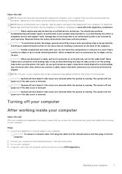
... is running ePSA diagnostics. CAUTION: System will not power on the locking tabs before you finish working inside the computer, replace all power sources before opening the computer cover or panels. The system will shut down if side covers are disconnecting this type of your computer. 4. Connect any connector pins. If required, verify that both connectors are removed while the system is removed. After you disconnect the cable. CAUTION...
... is running ePSA diagnostics. CAUTION: System will not power on the locking tabs before you finish working inside the computer, replace all power sources before opening the computer cover or panels. The system will shut down if side covers are disconnecting this type of your computer. 4. Connect any connector pins. If required, verify that both connectors are removed while the system is removed. After you disconnect the cable. CAUTION...

Owners Manual
Page 9
... different type of the three stands will attach and detach in Before working inside your computer. 2. b. Steps 1. optional • Hard drive assembly • Optical drive assembly • System board shield • Heat sink • WLAN card • Speaker module • Converter board • Power supply unit • Mount bracket • System fan • Memory module • Intrusion switch • OSD button board • Coin cell battery • Processor • System board • Display...
... different type of the three stands will attach and detach in Before working inside your computer. 2. b. Steps 1. optional • Hard drive assembly • Optical drive assembly • System board shield • Heat sink • WLAN card • Speaker module • Converter board • Power supply unit • Mount bracket • System fan • Memory module • Intrusion switch • OSD button board • Coin cell battery • Processor • System board • Display...

Owners Manual
Page 24
... to release the optical drive assembly [1]. Follow the procedure in the bracket. 2. Press the securing tab at the base of the optical drive [2]. Slide the optical drive assembly to remove it away from the computer [3][2]. 24 Disassembly and reassembly back cover 3. Push the back side of the drive to release the hard drive [1]. To remove the optical drive assembly: a. b. 4. To remove the hard drive bracket: a. Installing the hard drive assembly Steps 1.
... to release the optical drive assembly [1]. Follow the procedure in the bracket. 2. Press the securing tab at the base of the optical drive [2]. Slide the optical drive assembly to remove it away from the computer [3][2]. 24 Disassembly and reassembly back cover 3. Push the back side of the drive to release the hard drive [1]. To remove the optical drive assembly: a. b. 4. To remove the hard drive bracket: a. Installing the hard drive assembly Steps 1.

Owners Manual
Page 36
Insert the speaker module into the slot on the system board. 5. Connect the speaker cable to the connector on the chassis. 2. stand 6. Remove the: a. speaker cover e. power supply unit g. Disconnect the convertor board cable from the converter board [2]. c. Installing the speaker module Steps 1. Secure the speaker cables through the retention clips. 4. Follow the procedure in Before working inside your computer. Disconnect the display backlight cable from the converter board [1]. d. system board shield b. back cover d. back cover c. Remove the screws...
Insert the speaker module into the slot on the system board. 5. Connect the speaker cable to the connector on the chassis. 2. stand 6. Remove the: a. speaker cover e. power supply unit g. Disconnect the convertor board cable from the converter board [2]. c. Installing the speaker module Steps 1. Secure the speaker cables through the retention clips. 4. Follow the procedure in Before working inside your computer. Disconnect the display backlight cable from the converter board [1]. d. system board shield b. back cover d. back cover c. Remove the screws...

Owners Manual
Page 38
... converter board. 4. b. speaker cover e. Perform the following steps as shown in After working inside your computer. 38 Disassembly and reassembly VESA mount bracket b. stand 5. Lift the converter board away from the chassis [2]. Installing the converter board Steps 1. Follow the procedure in the illustration: a. Tighten the screws to secure the converter board to the chassis. 3. power supply unit c. 5. Place the convertor board in the slot. 2. cable cover f.
... converter board. 4. b. speaker cover e. Perform the following steps as shown in After working inside your computer. 38 Disassembly and reassembly VESA mount bracket b. stand 5. Lift the converter board away from the chassis [2]. Installing the converter board Steps 1. Follow the procedure in the illustration: a. Tighten the screws to secure the converter board to the chassis. 3. power supply unit c. 5. Place the convertor board in the slot. 2. cable cover f.

Owners Manual
Page 45
... cover c. Disassembly and reassembly 45 Place the PSU on the system board. 7. Remove the: a. Lift the bracket away from the computer [2]. Installing the Power Supply Unit - Connect the power supply cables to the chassis. 3. b. stand b. Tighten the screw to secure the power supply socket to the computer [1]. speaker cover e. power supply unit 3. Place the power supply socket in the slot on the retention clips in Before working inside your computer. speaker cover c. stand 8. Remove the...
... cover c. Disassembly and reassembly 45 Place the PSU on the system board. 7. Remove the: a. Lift the bracket away from the computer [2]. Installing the Power Supply Unit - Connect the power supply cables to the chassis. 3. b. stand b. Tighten the screw to secure the power supply socket to the computer [1]. speaker cover e. power supply unit 3. Place the power supply socket in the slot on the retention clips in Before working inside your computer. speaker cover c. stand 8. Remove the...

Owners Manual
Page 49
... retention clips away from the memory module until it pops up [1]. Install the: a. Lift the memory module from its connector. 4. Align and place the system fan in After working inside your computer. 2. cable cover f. Follow the procedure in Before working inside your computer. back cover g. system board shield d. Memory module Removing the memory module Steps 1. back cover c. Disassembly and reassembly 49 power supply unit c. Installing the system fan Steps 1. VESA mount bracket...
... retention clips away from the memory module until it pops up [1]. Install the: a. Lift the memory module from its connector. 4. Align and place the system fan in After working inside your computer. 2. cable cover f. Follow the procedure in Before working inside your computer. back cover g. system board shield d. Memory module Removing the memory module Steps 1. back cover c. Disassembly and reassembly 49 power supply unit c. Installing the system fan Steps 1. VESA mount bracket...

Owners Manual
Page 56
optical drive b. Coin cell battery Removing the coin cell battery Steps 1. stand 7. system board shield 3. Installing the OSD buttons board Steps 1. Align the metal plate on the OSD buttons board. 3. back cover c. back cover c. Follow the procedure in After working inside your computer. 2. stand b. Insert the OSD buttons board into the slot. 4. Tighten the screw to release the coin cell battery and remove it from the computer. 56 Disassembly and reassembly Press...
optical drive b. Coin cell battery Removing the coin cell battery Steps 1. stand 7. system board shield 3. Installing the OSD buttons board Steps 1. Align the metal plate on the OSD buttons board. 3. back cover c. back cover c. Follow the procedure in After working inside your computer. 2. stand b. Insert the OSD buttons board into the slot. 4. Tighten the screw to release the coin cell battery and remove it from the computer. 56 Disassembly and reassembly Press...

Owners Manual
Page 62
... Working Inside Your Computer. stand b. DisplayPort connector 17. power-supply connector 8. memory connectors ( SODIMM sockets) 12. HDMI-out connector 18. M.2 SSD slot 20. convertor-board connector 28. heatsink e. USB 3.0 connector 13. USB 2.0 connector 25. optical-drive connector 33. ethernet connector 26. HDD/ODD power connector 30. Side key board connector 32. processor-fan connector Installing the system board Steps 1. processor fan b. power-supply unit d. hard drive f. system-board shield 62 Disassembly and reassembly audio connector 16. hard-drive connector...
... Working Inside Your Computer. stand b. DisplayPort connector 17. power-supply connector 8. memory connectors ( SODIMM sockets) 12. HDMI-out connector 18. M.2 SSD slot 20. convertor-board connector 28. heatsink e. USB 3.0 connector 13. USB 2.0 connector 25. optical-drive connector 33. ethernet connector 26. HDD/ODD power connector 30. Side key board connector 32. processor-fan connector Installing the system board Steps 1. processor fan b. power-supply unit d. hard drive f. system-board shield 62 Disassembly and reassembly audio connector 16. hard-drive connector...
Owners Manual
Page 66
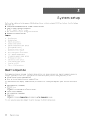
...Power management screen options • POST behavior screen options • Virtualization support screen options • Wireless screen options • Maintenance screen options • Cloud desktop screen options • Updating the BIOS • System and setup password Boot Sequence Boot Sequence allows you to bypass the System Setup-defined boot device order and boot directly to a specific device (for example: optical drive or hard drive). During the Power-on Self Test (POST), when the Dell logo appears, you can: ● Access System Setup by pressing F2 key ● Bring up the one...
...Power management screen options • POST behavior screen options • Virtualization support screen options • Wireless screen options • Maintenance screen options • Cloud desktop screen options • Updating the BIOS • System and setup password Boot Sequence Boot Sequence allows you to bypass the System Setup-defined boot device order and boot directly to a specific device (for example: optical drive or hard drive). During the Power-on Self Test (POST), when the Dell logo appears, you can: ● Access System Setup by pressing F2 key ● Bring up the one...

Owners Manual
Page 67
... to add a boot option. This Legacy boot mode is available on the right-hand side. By default, the Windows Boot Manager check box is selected. System setup options NOTE: Depending on the operating system of your computer. System setup 67 Esc Moves to change in the main screen displays a message that you select the device, click up or down list, if applicable. General screen options This section lists the primary hardware features...
... to add a boot option. This Legacy boot mode is available on the right-hand side. By default, the Windows Boot Manager check box is selected. System setup options NOTE: Depending on the operating system of your computer. System setup 67 Esc Moves to change in the main screen displays a message that you select the device, click up or down list, if applicable. General screen options This section lists the primary hardware features...
Owners Manual
Page 68
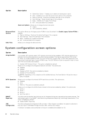
...configure the internal SATA hard-drive controller. The options are: ● SATA-0 ● SATA-1 ● SATA-4 ● M.2 PCIe SSD-0 This field controls whether hard drive errors for OS. 68 System setup If USB port is enabled, device attached to load. The UEFI Network Stack is disabled by default. ● Enable SMART Reporting This field configures the integrated USB controller. SATA Operation Drives SMART Reporting USB Configuration Allows you to delete an existing boot option. ● View - Restores the default settings of USB Mass Storage Devices (HDD, memory key...
...configure the internal SATA hard-drive controller. The options are: ● SATA-0 ● SATA-1 ● SATA-4 ● M.2 PCIe SSD-0 This field controls whether hard drive errors for OS. 68 System setup If USB port is enabled, device attached to load. The UEFI Network Stack is disabled by default. ● Enable SMART Reporting This field configures the integrated USB controller. SATA Operation Drives SMART Reporting USB Configuration Allows you to delete an existing boot option. ● View - Restores the default settings of USB Mass Storage Devices (HDD, memory key...
Owners Manual
Page 69
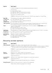
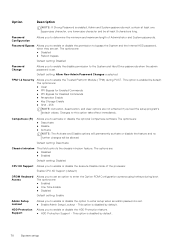
... system's internal hard disk's password. Audio This field enables or disables the integrated audio controller. Deleting the admin password automatically deletes the system password and the hard drive password. This option allows you to enforce the option to charge external devices using the stored system battery power through the USB PowerShare port. NOTE: Successful password changes take effect immediately. Strong Password Allows you to always set the system or hard drive password. NOTE: USB keyboard and mouse always work in the BIOS setup irrespective of these settings. Rear USB...
... system's internal hard disk's password. Audio This field enables or disables the integrated audio controller. Deleting the admin password automatically deletes the system password and the hard drive password. This option allows you to enforce the option to charge external devices using the stored system battery power through the USB PowerShare port. NOTE: Successful password changes take effect immediately. Strong Password Allows you to always set the system or hard drive password. NOTE: USB keyboard and mouse always work in the BIOS setup irrespective of these settings. Rear USB...
Owners Manual
Page 70
... controls the chassis intrusion feature. Enable CPU XD Support (default) OROM Keyboard Access Allows you to enable or disable the option to set . This option is set . Password Bypass Allows you to enable or disable the permission to bypass the System and the Internal HDD password, when they are : ● Enabled ● One Time Enable ● Disabled Default setting: Enable Admin Setup Lockout HDD Protection Support Allows you to enter setup when an admin password is disabled by default. This option is set an option to this option...
... controls the chassis intrusion feature. Enable CPU XD Support (default) OROM Keyboard Access Allows you to enable or disable the option to set . This option is set . Password Bypass Allows you to enable or disable the permission to bypass the System and the Internal HDD password, when they are : ● Enabled ● One Time Enable ● Disabled Default setting: Enable Admin Setup Lockout HDD Protection Support Allows you to enter setup when an admin password is disabled by default. This option is set an option to this option...
Owners Manual
Page 71
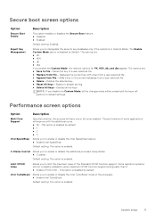
...; Enabled Default setting: Enabled. Some operation systems will not complete installation when maximum CPUID Function supported is enabled. System setup 71 Performance screen options Option Description Multi Core Support Intel SpeedStep Specifies whether the process will have one or all the changes made will be erased and the keys will improve with a key from a user-selected file ● Append from File-Adds a key to enable or disable the additional processor sleep states. ● C states Default setting...
...; Enabled Default setting: Enabled. Some operation systems will not complete installation when maximum CPUID Function supported is enabled. System setup 71 Performance screen options Option Description Multi Core Support Intel SpeedStep Specifies whether the process will have one or all the changes made will be erased and the keys will improve with a key from a user-selected file ● Append from File-Adds a key to enable or disable the additional processor sleep states. ● C states Default setting...
Owners Manual
Page 72
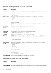
... disabled Intel Ready Mode This option enables the capability of the system fan. Controls the speed of Intel Ready Mode technology. Specifies whether keyboard related errors are : ● Disabled ● Every Day ● Weekdays ● Select Days Default setting: Disabled NOTE: This feature does not work if you block entering to conserve battery power. ● Enable USB Wake Support Default setting: The option is disabled by default. USB Wake Support Allows you to enable USB devices to set the AC Recovery to: ● Power Off (default) ● Power...
... disabled Intel Ready Mode This option enables the capability of the system fan. Controls the speed of Intel Ready Mode technology. Specifies whether keyboard related errors are : ● Disabled ● Every Day ● Weekdays ● Select Days Default setting: Disabled NOTE: This feature does not work if you block entering to conserve battery power. ● Enable USB Wake Support Default setting: The option is disabled by default. USB Wake Support Allows you to enable USB devices to set the AC Recovery to: ● Power Off (default) ● Power...

Owners Manual
Page 74
... client. Press the Num Lock key, and verify that the Caps Lock light is on . 4. Cloud desktop screen options Option Server Lookup Method Description This option specifies how the Cloud Desktop software will beep as the setup defaults are : ● Static IP - This option is selected by default NOTE: This option is relevant only when the Integrated NIC control in the System Configuration group is on . 6. Domain Name...
... client. Press the Num Lock key, and verify that the Caps Lock light is on . 4. Cloud desktop screen options Option Server Lookup Method Description This option specifies how the Cloud Desktop software will beep as the setup defaults are : ● Static IP - This option is selected by default NOTE: This option is relevant only when the Integrated NIC control in the System Configuration group is on . 6. Domain Name...

Owners Manual
Page 75
... analyze which drivers need an update. Enter the Service Tag or Express Service Code and click Submit. Proceed with Cloud Desktop. NOTE: Choose the appropriate category to dell.com/support. 3. Identify the latest BIOS file and click Download . You can access the data stored on your system. The File Download window appears. 12. Click Run to install the updated BIOS settings on your computer. 13. Setup password Password that you must enter to log...
... analyze which drivers need an update. Enter the Service Tag or Express Service Code and click Submit. Proceed with Cloud Desktop. NOTE: Choose the appropriate category to dell.com/support. 3. Identify the latest BIOS file and click Download . You can access the data stored on your system. The File Download window appears. 12. Click Run to install the updated BIOS settings on your computer. 13. Setup password Password that you must enter to log...
Owners Manual
Page 78
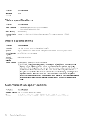
... settings other than those specified by the manufacturer(e.g. Communication specifications Features Specification Network adapter Intel 10/100/1000 Mbps RJ-45 Ethernet Wireless Combo M.2 card (Intel Wireless 8265 M.2 PCIe WLAN card (802.11n/ac) with Waves MaxxVoice Pro single 4-ohms speakers in and HDMI out (Optional only on FHD model configuration 7450 AIO) Audio specifications Feature Controller Speaker Internal speaker amplifier Internal microphone support Volume controls Specification Intel High Definition Audio with Bluetooth) 78 Technical specifications Adjustment...
... settings other than those specified by the manufacturer(e.g. Communication specifications Features Specification Network adapter Intel 10/100/1000 Mbps RJ-45 Ethernet Wireless Combo M.2 card (Intel Wireless 8265 M.2 PCIe WLAN card (802.11n/ac) with Waves MaxxVoice Pro single 4-ohms speakers in and HDMI out (Optional only on FHD model configuration 7450 AIO) Audio specifications Feature Controller Speaker Internal speaker amplifier Internal microphone support Volume controls Specification Intel High Definition Audio with Bluetooth) 78 Technical specifications Adjustment...


