
User Manual
Page 8
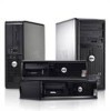
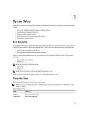
Figure 13. Turning On Power Specifications NOTE: Offerings may vary by law to view information about your computer. For more information regarding the configuration of your computer, click Start → Help and Support and select the option to ship with your computer. 8 Network Connection 4. The following specifications are only those required by region. Connecting Power 5. Figure 12. Figure 11. Press the power buttons on the monitor and the computer. Connect the network cable (optional). Connect the power cable(s). 3.
Figure 13. Turning On Power Specifications NOTE: Offerings may vary by law to view information about your computer. For more information regarding the configuration of your computer, click Start → Help and Support and select the option to ship with your computer. 8 Network Connection 4. The following specifications are only those required by region. Connecting Power 5. Figure 12. Figure 11. Press the power buttons on the monitor and the computer. Connect the network cable (optional). Connect the power cable(s). 3.

Owner's Manual (Desktop)
Page 4
......49 4 Diagnostics...51 Enhanced Pre-Boot System Assessment (ePSA) Diagnostics 51 5 Troubleshooting Your Computer 53 Power LED Diagnostics...53 Beep Code...54 Error Messages...54 6 Specifications...57 7 Contacting Dell ...65
......49 4 Diagnostics...51 Enhanced Pre-Boot System Assessment (ePSA) Diagnostics 51 5 Troubleshooting Your Computer 53 Power LED Diagnostics...53 Beep Code...54 Error Messages...54 6 Specifications...57 7 Contacting Dell ...65

Owner's Manual (Desktop)
Page 39
... most of the system setup options, changes that you can boot from including the diagnostic option. During the Power-on Self Test (POST), when the Dell logo appears, you can : • Change the NVRAM settings after you add or remove hardware • View the system hardware configuration • Enable or disable... to manage your computer security Boot Sequence Boot Sequence allows you to bypass the System Setup‐defined boot device order and boot directly to a specific device (for example: optical drive or hard drive).
... most of the system setup options, changes that you can boot from including the diagnostic option. During the Power-on Self Test (POST), when the Dell logo appears, you can : • Change the NVRAM settings after you add or remove hardware • View the system hardware configuration • Enable or disable... to manage your computer security Boot Sequence Boot Sequence allows you to bypass the System Setup‐defined boot device order and boot directly to a specific device (for example: optical drive or hard drive).
Owner's Manual (Desktop)
Page 41
... boot any device attached to this port is enabled, device attached to configure the operating mode of the SMART (Self Monitoring Analysis and Reporting Technology) specification. • Enable SMART Reporting -
... boot any device attached to this port is enabled, device attached to configure the operating mode of the SMART (Self Monitoring Analysis and Reporting Technology) specification. • Enable SMART Reporting -

Owner's Manual (Desktop)
Page 51
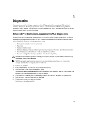
... problem yourself, service and support personnel can use the diagnostics results to help you wish to run the ePSA diagnostics before contacting Dell for specific devices require user interaction. Enhanced Pre-Boot System Assessment (ePSA) Diagnostics The ePSA diagnostics (also known as the... Dell logo appears. 3. If you solve the problem. Always ensure that inform you experience a problem with other computers may cause invalid results or error...
... problem yourself, service and support personnel can use the diagnostics results to help you wish to run the ePSA diagnostics before contacting Dell for specific devices require user interaction. Enhanced Pre-Boot System Assessment (ePSA) Diagnostics The ePSA diagnostics (also known as the... Dell logo appears. 3. If you solve the problem. Always ensure that inform you experience a problem with other computers may cause invalid results or error...

Owner's Manual (Desktop)
Page 55
... the command. Memory double word logic failure at address, read value expecting value A memory module may be faulty or improperly seated. Memory tests terminated by specific information-for example, Printer out of memory recorded in the computer configuration information does not match the memory installed in System Setup may be malfunctioning...
... the command. Memory double word logic failure at address, read value expecting value A memory module may be faulty or improperly seated. Memory tests terminated by specific information-for example, Printer out of memory recorded in the computer configuration information does not match the memory installed in System Setup may be malfunctioning...
Owner's Manual (Desktop)
Page 56
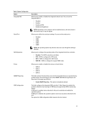
...be loose. Sector not found The operating system cannot read from the floppy or hard drive, the computer could not find a specific track on selected drive The operating system cannot write to drive is not the only bootable drive, enter System Setup and change the... Unexpected interrupt in System Setup does not match the computer clock. It is operating outside of -day not set operation failed. WARNING: Dell's Disk Monitoring During initial startup, the drive detected possible error conditions. Read fault The operating system cannot read from the computer. Shutdown ...
...be loose. Sector not found The operating system cannot read from the floppy or hard drive, the computer could not find a specific track on selected drive The operating system cannot write to drive is not the only bootable drive, enter System Setup and change the... Unexpected interrupt in System Setup does not match the computer clock. It is operating outside of -day not set operation failed. WARNING: Dell's Disk Monitoring During initial startup, the drive detected possible error conditions. Read fault The operating system cannot read from the computer. Shutdown ...
Owner's Manual (Desktop)
Page 57
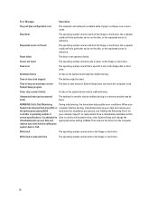
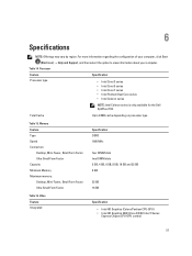
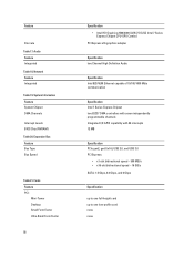
..., Mini-Tower, Small Form Factor Ultra Small Form Factor Capacity Minimum Memory Maximum memory: Desktop, Mini-Tower, Small Form Factor Ultra Small Form Factor Specification DDR3 1600 MHz four DIMM slots two DIMM slots 2 GB, 4 GB, 6 GB, 8 GB, 16 GB and 32 GB 2 GB 32... Table 16. Processor Feature Specification Processor type • Intel Core i3 series • Intel Core i5 series • Intel Core i7 series • Intel Pentium Dual Core series • Intel Celeron series NOTE: Intel Celeron series is only available for the Dell OptiPlex 7010. For more information regarding...
..., Mini-Tower, Small Form Factor Ultra Small Form Factor Capacity Minimum Memory Maximum memory: Desktop, Mini-Tower, Small Form Factor Ultra Small Form Factor Specification DDR3 1600 MHz four DIMM slots two DIMM slots 2 GB, 4 GB, 6 GB, 8 GB, 16 GB and 32 GB 2 GB 32... Table 16. Processor Feature Specification Processor type • Intel Core i3 series • Intel Core i5 series • Intel Core i7 series • Intel Pentium Dual Core series • Intel Celeron series NOTE: Intel Celeron series is only available for the Dell OptiPlex 7010. For more information regarding...
Owner's Manual (Desktop)
Page 58
...Intel 7 Series Express Chipset CPU-GPU Combo) PCI Express x16 graphics adapter Specification two Channel High Definition Audio Specification Intel 82579LM Ethernet capable of 10/100/1000 Mb/s communication Specification Intel 7 Series Express Chipset two 82C37 DMA controllers with seven independently programmable ...x1-slot bidirectional speed - 500 MB/s • x16-slot bidirectional speed - 16 GB/s SATA: 1.5 Gbps, 3.0 Gbps, and 6 Gbps Specification up to one full-height card up to one low-profile card none none System Information Feature System Chipset DMA Channels Interrupt Levels BIOS Chip...
...Intel 7 Series Express Chipset CPU-GPU Combo) PCI Express x16 graphics adapter Specification two Channel High Definition Audio Specification Intel 82579LM Ethernet capable of 10/100/1000 Mb/s communication Specification Intel 7 Series Express Chipset two 82C37 DMA controllers with seven independently programmable ...x1-slot bidirectional speed - 500 MB/s • x16-slot bidirectional speed - 16 GB/s SATA: 1.5 Gbps, 3.0 Gbps, and 6 Gbps Specification up to one full-height card up to one low-profile card none none System Information Feature System Chipset DMA Channels Interrupt Levels BIOS Chip...
Owner's Manual (Desktop)
Page 59
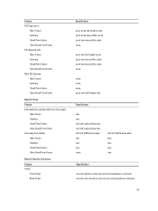
External Connectors Feature Audio: Front Panel Back Panel Specification up to three full-height cards up to three low-profile cards up to...two low-profile cards up to two low-profile cards none none none none up to one half-height card Specification two one one slim optical drive bay one slim optical drive bay 3.5-inch SATA drive bays two one one ...none 2.5-inch SATA drive bays two two two one Specification one microphone connector and one headphone connector one line-out connector and one line-in/microphone connector 59 Feature PCI ...
External Connectors Feature Audio: Front Panel Back Panel Specification up to three full-height cards up to three low-profile cards up to...two low-profile cards up to two low-profile cards none none none none up to one half-height card Specification two one one slim optical drive bay one slim optical drive bay 3.5-inch SATA drive bays two one one ...none 2.5-inch SATA drive bays two two two one Specification one microphone connector and one headphone connector one line-out connector and one line-in/microphone connector 59 Feature PCI ...

Owner's Manual (Desktop)
Page 60
...Ultra Small Form Factor one 164-pin connector Ultra Small Form Factor none Mini PCI Express data width (maximum) - Internal Connectors Feature Specification PCI 2.3 data width (maximum) - 32 bits: Mini-Tower and Desktop one 36-pin connector Small Form Factor and Ultra Small...data width (maximum) - Feature Network Adapter Serial Parallel USB 2.0: Mini-Tower, Desktop, Small Form Factor Ultra Small Form Factor USB 3.0: Video Specification one RJ45 connector one 9-pin connector; 16550 C compatible one 25-pin connector (optional for mini-tower, desktop and small form factor) Front ...
...Ultra Small Form Factor one 164-pin connector Ultra Small Form Factor none Mini PCI Express data width (maximum) - Internal Connectors Feature Specification PCI 2.3 data width (maximum) - 32 bits: Mini-Tower and Desktop one 36-pin connector Small Form Factor and Ultra Small...data width (maximum) - Feature Network Adapter Serial Parallel USB 2.0: Mini-Tower, Desktop, Small Form Factor Ultra Small Form Factor USB 3.0: Video Specification one RJ45 connector one 9-pin connector; 16550 C compatible one 25-pin connector (optional for mini-tower, desktop and small form factor) Front ...
Owner's Manual (Desktop)
Page 61
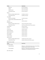
...the computer is reading data from or writing data to the hard drive. 61 blinking white light indicates sleep state of the computer: Specification White light - Controls and Lights Feature Front of the computer: Power button light Drive activity light Back of the computer. Feature... Specification Mini-Tower four 7-pin connectors Desktop three 7-pin connectors Small Form Factor three 7-pin connectors Ultra Small Form Factor two 7-pin connectors Memory:...
...the computer is reading data from or writing data to the hard drive. 61 blinking white light indicates sleep state of the computer: Specification White light - Controls and Lights Feature Front of the computer: Power button light Drive activity light Back of the computer. Feature... Specification Mini-Tower four 7-pin connectors Desktop three 7-pin connectors Small Form Factor three 7-pin connectors Ultra Small Form Factor two 7-pin connectors Memory:...
Owner's Manual (Desktop)
Page 62
... Mbps connection exists between the network and the computer. Off (no light) - The power supply is turned on integrated network adapter Power supply diagnostic light Specification Green - Power NOTE: Heat dissipation is present. The power cable must be connected to 60 Hz, 2.9 A 3 V CR2032 lithium coin cell Table 27. Power Mini-Tower...
... Mbps connection exists between the network and the computer. Off (no light) - The power supply is turned on integrated network adapter Power supply diagnostic light Specification Green - Power NOTE: Heat dissipation is present. The power cable must be connected to 60 Hz, 2.9 A 3 V CR2032 lithium coin cell Table 27. Power Mini-Tower...

Owner's Manual (Desktop)
Page 63
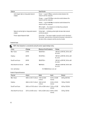
Environmental Feature Temperature range: Operating Storage Relative humidity (maximum): Operating Storage Maximum vibration: Operating Storage Maximum shock: Operating Storage Altitude: Operating Storage Airborne contaminant level Specification 10 °C to 35 °C (50 °F to 95 °F) -40 °C to 65 °C (-40 °F to 149 °F) 20% to 80% (non-condensing) 5% to 95% (non-condensing) 0.26 GRMS 2.20 GRMS 40 G 105 G -15.20 m to 3048 m (-50 ft to 10,000 ft) -15.20 m to 10,668 m (-50 ft to 35,000 ft) G1 or lower as defined by ANSI/ISA-S71.04-1985 63 Table 28.
Environmental Feature Temperature range: Operating Storage Relative humidity (maximum): Operating Storage Maximum vibration: Operating Storage Maximum shock: Operating Storage Altitude: Operating Storage Airborne contaminant level Specification 10 °C to 35 °C (50 °F to 95 °F) -40 °C to 65 °C (-40 °F to 149 °F) 20% to 80% (non-condensing) 5% to 95% (non-condensing) 0.26 GRMS 2.20 GRMS 40 G 105 G -15.20 m to 3048 m (-50 ft to 10,000 ft) -15.20 m to 10,668 m (-50 ft to 35,000 ft) G1 or lower as defined by ANSI/ISA-S71.04-1985 63 Table 28.

Owner's Manual (Mini-Tower)
Page 4
......45 4 Diagnostics...47 Enhanced Pre-Boot System Assessment (ePSA) Diagnostics 47 5 Troubleshooting Your Computer 49 Power LED Diagnostics...49 Beep Code...50 Error Messages...50 6 Specifications...53 7 Contacting Dell ...61
......45 4 Diagnostics...47 Enhanced Pre-Boot System Assessment (ePSA) Diagnostics 47 5 Troubleshooting Your Computer 49 Power LED Diagnostics...49 Beep Code...50 Error Messages...50 6 Specifications...53 7 Contacting Dell ...61
Owner's Manual (Mini-Tower)
Page 35
... and power management thresholds • Manage your computer hardware and specify BIOS‐level options. Table 1. During the Power-on Self Test (POST), when the Dell logo appears, you can : • Change the NVRAM settings after you restart the system. Down arrow Moves to manage your computer security Boot Sequence Boot... key The one-time boot menu displays the devices that you to bypass the System Setup‐defined boot device order and boot directly to a specific device (for example: optical drive or hard drive).
... and power management thresholds • Manage your computer hardware and specify BIOS‐level options. Table 1. During the Power-on Self Test (POST), when the Dell logo appears, you can : • Change the NVRAM settings after you restart the system. Down arrow Moves to manage your computer security Boot Sequence Boot... key The one-time boot menu displays the devices that you to bypass the System Setup‐defined boot device order and boot directly to a specific device (for example: optical drive or hard drive).

Owner's Manual (Mini-Tower)
Page 37
... integrated drives are hidden. • ATA - SATA is disabled, the operation system cannot see any type of the SMART (Self Monitoring Analysis and Reporting Technology) specification. • Enable SMART Reporting - This option is configured for operation system. You can set the serial port to define the serial port settings. If USB...
... integrated drives are hidden. • ATA - SATA is disabled, the operation system cannot see any type of the SMART (Self Monitoring Analysis and Reporting Technology) specification. • Enable SMART Reporting - This option is configured for operation system. You can set the serial port to define the serial port settings. If USB...
Owner's Manual (Mini-Tower)
Page 47
... all the detected devices. 4. If you wish to run the ePSA diagnostics before contacting Dell for technical assistance. Note the error code and contact Dell. 47 If you are displayed. Always ensure that inform you of options for specific devices require user interaction. On the boot menu screen, select the Diagnostics option. 4 Diagnostics...
... all the detected devices. 4. If you wish to run the ePSA diagnostics before contacting Dell for technical assistance. Note the error code and contact Dell. 47 If you are displayed. Always ensure that inform you of options for specific devices require user interaction. On the boot menu screen, select the Diagnostics option. 4 Diagnostics...

Owner's Manual (Mini-Tower)
Page 51
... DIMM1 seated or installed. Reinstall the memory modules and, if necessary, replace them . Memory size in System Setup may be faulty. Memory tests terminated by specific information-for example, Printer out of memory recorded in the computer configuration information does not match the memory installed in drive A does not have a bootable...
... DIMM1 seated or installed. Reinstall the memory modules and, if necessary, replace them . Memory size in System Setup may be faulty. Memory tests terminated by specific information-for example, Printer out of memory recorded in the computer configuration information does not match the memory installed in drive A does not have a bootable...

Owner's Manual (Mini-Tower)
Page 52
...hard drive, the computer could not find a particular sector on the disk, or the requested sector is immediately available and the normal specifications. Requested sector not found The operating system cannot locate a sector on the system board may be malfunctioning. Time-of -day clock... stopped The battery might be dead. WARNING: Dell's Disk Monitoring During initial startup, the drive detected possible error conditions. Timer chip counter 2 failed A chip on the floppy or hard drive...
...hard drive, the computer could not find a particular sector on the disk, or the requested sector is immediately available and the normal specifications. Requested sector not found The operating system cannot locate a sector on the system board may be malfunctioning. Time-of -day clock... stopped The battery might be dead. WARNING: Dell's Disk Monitoring During initial startup, the drive detected possible error conditions. Timer chip counter 2 failed A chip on the floppy or hard drive...


