
Service Manual
Page 2
...be used in this text: Dell, the DELL logo, and Latitude are registered trademarks of Dell Computer Corporation is strictly forbidden. June 1996 P/N 98085 All rights reserved. Dell Computer Corporation disclaims any manner whatsoever without notice. © 1994-1996 Dell Computer Corporation. Reproduction in any...Intel Corporation; Intel and Pentium are registered trademarks of Microsoft Corporation; Information in this manual is subject to either the entities claiming the marks and names or their products. MS-DOS is a registered trademark of Dell Computer Corporation;
...be used in this text: Dell, the DELL logo, and Latitude are registered trademarks of Dell Computer Corporation is strictly forbidden. June 1996 P/N 98085 All rights reserved. Dell Computer Corporation disclaims any manner whatsoever without notice. © 1994-1996 Dell Computer Corporation. Reproduction in any...Intel Corporation; Intel and Pentium are registered trademarks of Microsoft Corporation; Information in this manual is subject to either the entities claiming the marks and names or their products. MS-DOS is a registered trademark of Dell Computer Corporation;

Service Manual
Page 8
...NOTE provides helpful information about using the Dell diagnostics to test portable computers, and the online System User's Guide for information about system setup and operations. Warnings, Cautions, and Notes Throughout this manual, Dell provides the Reference and Troubleshooting Guide for... troubleshooting procedures and instructions on using the computer system. x In addition to service Dell portable computers is a basic knowledge of IBM-compatible PCs...
...NOTE provides helpful information about using the Dell diagnostics to test portable computers, and the online System User's Guide for information about system setup and operations. Warnings, Cautions, and Notes Throughout this manual, Dell provides the Reference and Troubleshooting Guide for... troubleshooting procedures and instructions on using the computer system. x In addition to service Dell portable computers is a basic knowledge of IBM-compatible PCs...
Service Manual
Page 12
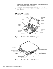
... number expansion connector PS/2 connector headphones/speakers connector external microphone connector AC adapter connector PC Card slots Figure 1-2. Front View of the Portable Computer 1-2 Dell Latitude LM Systems Service Manual Back View of the Portable Computer infrared port serial port connector parallel port connector monitor connector I /O panel. warm swapping. Physical Description LCD assembly status...
... number expansion connector PS/2 connector headphones/speakers connector external microphone connector AC adapter connector PC Card slots Figure 1-2. Front View of the Portable Computer 1-2 Dell Latitude LM Systems Service Manual Back View of the Portable Computer infrared port serial port connector parallel port connector monitor connector I /O panel. warm swapping. Physical Description LCD assembly status...
Service Manual
Page 14
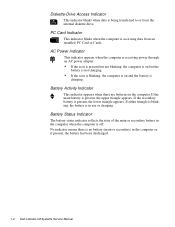
..., the battery is present, the upper triangle appears. If the main battery is in the computer or, if present, the battery has been discharged. 1-4 Dell Latitude LM Systems Service Manual No indicator means there is accessing data from the internal diskette drive. PC Card Indicator This indicator blinks when the computer is no battery...
..., the battery is present, the upper triangle appears. If the main battery is in the computer or, if present, the battery has been discharged. 1-4 Dell Latitude LM Systems Service Manual No indicator means there is accessing data from the internal diskette drive. PC Card Indicator This indicator blinks when the computer is no battery...
Service Manual
Page 16
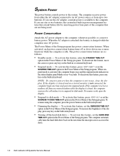
... goes into suspend mode. To deactivate the feature, move the cursor or press any key on the next time the microprocessor accesses the drive. 1-6 Dell Latitude LM Systems Service Manual NOTE: To conserve power when the computer is activated, the computer beeps once and the suspend mode indicator in keyboard. To resume work, open...
... goes into suspend mode. To deactivate the feature, move the cursor or press any key on the next time the microprocessor accesses the drive. 1-6 Dell Latitude LM Systems Service Manual NOTE: To conserve power when the computer is activated, the computer beeps once and the suspend mode indicator in keyboard. To resume work, open...

Service Manual
Page 18
must be installed in matched pairs Standard RAM 8 MB on system board Maximum RAM 40 MB 1-8 Dell Latitude LM Systems Service Manual and 5-V PC Card connector size . . . . . 68 pins Data width (maximum) . . . . . 32 bits Memory Architecture fast-page mode, two-way interleaved Memory module capacities . . 4, 8, and 16 ...
must be installed in matched pairs Standard RAM 8 MB on system board Maximum RAM 40 MB 1-8 Dell Latitude LM Systems Service Manual and 5-V PC Card connector size . . . . . 68 pins Data width (maximum) . . . . . 32 bits Memory Architecture fast-page mode, two-way interleaved Memory module capacities . . 4, 8, and 16 ...

Service Manual
Page 20
...) Maximum resolution 800 x 600 pixels; 256 colors Refresh rate (typical 70 Hz Response time (typical) . . . . . 300 ms Operating angle 0° (closed) to 135° 1-10 Dell Latitude LM Systems Service Manual
...) Maximum resolution 800 x 600 pixels; 256 colors Refresh rate (typical 70 Hz Response time (typical) . . . . . 300 ms Operating angle 0° (closed) to 135° 1-10 Dell Latitude LM Systems Service Manual

Service Manual
Page 22
... features such as charge time, operating time, and life span can vary according to the conditions under which the computer and battery are used. 1-12 Dell Latitude LM Systems Service Manual
... features such as charge time, operating time, and life span can vary according to the conditions under which the computer and battery are used. 1-12 Dell Latitude LM Systems Service Manual

Service Manual
Page 24
... 2438 m (0 ft to 8,000 ft) Storage 0 m to 12,192 m (0 ft to 40,000 ft) 2 Measured with the hard-disk drive in head-parked position. 1-14 Dell Latitude LM Systems Service Manual
... 2438 m (0 ft to 8,000 ft) Storage 0 m to 12,192 m (0 ft to 40,000 ft) 2 Measured with the hard-disk drive in head-parked position. 1-14 Dell Latitude LM Systems Service Manual

Service Manual
Page 26
... off, press any obvious physical damage, and then reinstall the modules. 9. Remove the diskette drive (if installed), verify that its associated buttons operate freely. 2-2 Dell Latitude LM Systems Service Manual If the display is properly connected to both the AC adapter and the wall outlet. c. Press the test button located on , go to see...
... off, press any obvious physical damage, and then reinstall the modules. 9. Remove the diskette drive (if installed), verify that its associated buttons operate freely. 2-2 Dell Latitude LM Systems Service Manual If the display is properly connected to both the AC adapter and the wall outlet. c. Press the test button located on , go to see...

Service Manual
Page 28
... indicators should light up within seconds after the system boots. Does the Diagnostics Menu appear on . Proceed to the next section, "Eliminating Resource Conflicts." 2-4 Dell Latitude LM Systems Service Manual If either of the diagnostics diskette into the diskette drive, and reboot the computer. No. If the computer emits a beep code, refer to step...
... indicators should light up within seconds after the system boots. Does the Diagnostics Menu appear on . Proceed to the next section, "Eliminating Resource Conflicts." 2-4 Dell Latitude LM Systems Service Manual If either of the diagnostics diskette into the diskette drive, and reboot the computer. No. If the computer emits a beep code, refer to step...

Service Manual
Page 32
... of low byte on memory faulty main board bus Check ROM copyright notice failure Faulty main board Interrupt mask register failure Faulty main board 3-2 Dell Latitude LM Systems Service Manual Beep Code 1-2 1-2-2-3 1-3-1-1 1-3-1-3 1-3-4-1 1-3-4-3 1-4-1-1 2-1-2-3 2-2-3-1 Table 3-1. POST Beep Codes Error Probable Causes Memory module not being properly identified or used Faulty memory module or faulty main board...
... of low byte on memory faulty main board bus Check ROM copyright notice failure Faulty main board Interrupt mask register failure Faulty main board 3-2 Dell Latitude LM Systems Service Manual Beep Code 1-2 1-2-2-3 1-3-1-1 1-3-1-3 1-3-4-1 1-3-4-3 1-4-1-1 2-1-2-3 2-2-3-1 Table 3-1. POST Beep Codes Error Probable Causes Memory module not being properly identified or used Faulty memory module or faulty main board...
Service Manual
Page 34
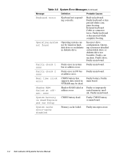
... check 1 nnnn Parity error in keyboard: Faulty keyboard or key pressed while computer booting. Built-in system Faulty main board. Incorrect drive configuration. Faulty microprocessor. 3-4 Dell Latitude LM Systems Service Manual Faulty keyboard or key pressed while computer booting. NVRAM may be found Operating system cannot be dead.
... check 1 nnnn Parity error in keyboard: Faulty keyboard or key pressed while computer booting. Built-in system Faulty main board. Incorrect drive configuration. Faulty microprocessor. 3-4 Dell Latitude LM Systems Service Manual Faulty keyboard or key pressed while computer booting. NVRAM may be found Operating system cannot be dead.

Service Manual
Page 36
... diskette contains the following options or exit to the MS-DOS® prompt: • RUN QUICK TESTS - Tests the primary functions of the computer 3-6 Dell Latitude LM Systems Service Manual Tests the mouse/touch pad subsystem • Diskette Drives - Tests the IDE hard-disk drive subsystem • IDE CD ROM Drives - Tests a SCSI hard...
... diskette contains the following options or exit to the MS-DOS® prompt: • RUN QUICK TESTS - Tests the primary functions of the computer 3-6 Dell Latitude LM Systems Service Manual Tests the mouse/touch pad subsystem • Diskette Drives - Tests the IDE hard-disk drive subsystem • IDE CD ROM Drives - Tests a SCSI hard...

Service Manual
Page 38
Before installing a screw, match the screw to the screw length graphics provided to check for correct length. 4-2 Dell Latitude LM Systems Service Manual Make sure that the correct length screw be used when reinstalling a screw. • Small scribe (or Delrin [plastic] screwdriver) • Nut drivers • Chip removal ...
Before installing a screw, match the screw to the screw length graphics provided to check for correct length. 4-2 Dell Latitude LM Systems Service Manual Make sure that the correct length screw be used when reinstalling a screw. • Small scribe (or Delrin [plastic] screwdriver) • Nut drivers • Chip removal ...

Service Manual
Page 40
... the way to load. The CD-ROM can be in the computer before or during boot in suspend mode. Options Bay Lock and Latch 4-4 Dell Latitude LM Systems Service Manual handle cover HD1 HD2 Figure 4-4. However, the CD-ROM must be inserted or removed while the computer is sometimes called hot swapping. Remove the...
... the way to load. The CD-ROM can be in the computer before or during boot in suspend mode. Options Bay Lock and Latch 4-4 Dell Latitude LM Systems Service Manual handle cover HD1 HD2 Figure 4-4. However, the CD-ROM must be inserted or removed while the computer is sometimes called hot swapping. Remove the...

Service Manual
Page 42
... and then the other end. While holding the cable in the center. . To ensure a firm connection, make sure the ZIF connector is completely closed. 4-6 Dell Latitude LM Systems Service Manual These connectors are fragile. To disconnect an interface cable from them carefully. Some ZIFs (keyboard connector on the movable part of the connector. Pull...
... and then the other end. While holding the cable in the center. . To ensure a firm connection, make sure the ZIF connector is completely closed. 4-6 Dell Latitude LM Systems Service Manual These connectors are fragile. To disconnect an interface cable from them carefully. Some ZIFs (keyboard connector on the movable part of the connector. Pull...

Service Manual
Page 44
LCD panel front bezel LCD panel flex cable latch hinge (2) power/suspend indicator inverter board back bezel stiffener microphone inverter board connector Figure 4-10. Exploded View-LCD Assembly 4-8 Dell Latitude LM Systems Service Manual
LCD panel front bezel LCD panel flex cable latch hinge (2) power/suspend indicator inverter board back bezel stiffener microphone inverter board connector Figure 4-10. Exploded View-LCD Assembly 4-8 Dell Latitude LM Systems Service Manual

Service Manual
Page 48
... PLSTC,LWR,FD,LMP Cable, service kit* CUST,CBL,FD,INT/EXT,LMP Connector, cable CBL,FD,INT/EXT,LMP * Customer-replaceable unit (CRU) 4-12 Dell Latitude LM Systems Service Manual
... PLSTC,LWR,FD,LMP Cable, service kit* CUST,CBL,FD,INT/EXT,LMP Connector, cable CBL,FD,INT/EXT,LMP * Customer-replaceable unit (CRU) 4-12 Dell Latitude LM Systems Service Manual

Service Manual
Page 50
... lens, right CVR,PLSTC,IR,LMP Cover, hinge, left CVR,HNG,LF,LMP Cover, keyboard screws CVR,SCR,KYBD,LMP * Customer-replaceable unit (CRU) 4-14 Dell Latitude LM Systems Service Manual
... lens, right CVR,PLSTC,IR,LMP Cover, hinge, left CVR,HNG,LF,LMP Cover, keyboard screws CVR,SCR,KYBD,LMP * Customer-replaceable unit (CRU) 4-14 Dell Latitude LM Systems Service Manual


