Service Manual
Page 3
... Activity Indicator 1-4 Battery Indicator 1-4 Keyboard Indicators 1-5 Controlling Computer Power 1-5 Interrupt Assignments 1-6 Technical Specifications 1-7 Initial User Contact 2-1 Visual Inspection 2-2 Observing the Boot Routine 2-4 Eliminating Resource Conflicts 2-6 Getting Help 2-6 POST Error Codes 3-1 Battery Failure Codes 3-4 System Error Messages 3-5 Running the Dell Diagnostics 3-9 Recommended Tools 4-2 Precautionary Measures 4-2 Screw Identification and Tightening 4-3 ZIF Connectors 4-4 Field-Replaceable...
... Activity Indicator 1-4 Battery Indicator 1-4 Keyboard Indicators 1-5 Controlling Computer Power 1-5 Interrupt Assignments 1-6 Technical Specifications 1-7 Initial User Contact 2-1 Visual Inspection 2-2 Observing the Boot Routine 2-4 Eliminating Resource Conflicts 2-6 Getting Help 2-6 POST Error Codes 3-1 Battery Failure Codes 3-4 System Error Messages 3-5 Running the Dell Diagnostics 3-9 Recommended Tools 4-2 Precautionary Measures 4-2 Screw Identification and Tightening 4-3 ZIF Connectors 4-4 Field-Replaceable...
Service Manual
Page 5
... 4-46 Left Slider 4-47 System Board Assembly Removal 4-48 Exhaust Fan Removal 4-50 I/R Board Removal 4-51 Reserve Battery Installation 4-52 Table 1-1. Table 3-2. Interrupt Assignments 1-6 Technical Specifications 1-7 POST Error Codes 3-2 Battery Failure Codes 3-4 System Error Messages 3-5 Parts and Assemblies 4-5 vii Figure 4-15. Figure 4-18. Figure 4-8. Figure 4-11. Figure 4-19. Figure 4-20. Figure...
... 4-46 Left Slider 4-47 System Board Assembly Removal 4-48 Exhaust Fan Removal 4-50 I/R Board Removal 4-51 Reserve Battery Installation 4-52 Table 1-1. Table 3-2. Interrupt Assignments 1-6 Technical Specifications 1-7 POST Error Codes 3-2 Battery Failure Codes 3-4 System Error Messages 3-5 Parts and Assemblies 4-5 vii Figure 4-15. Figure 4-18. Figure 4-8. Figure 4-11. Figure 4-19. Figure 4-20. Figure...
Service Manual
Page 7
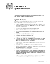
...and specifications of system memory. A CD-ROM drive for a battery in a Dell portable computer, the Latitude CP and CPi include the following new features: A Mobile Intel® Pentium® II microprocessor 233, 266, or 300 MHz or an Intel Pentium microprocessor with MMX technology 166, 200, or 233 MHz, ... time. Support for connecting external speakers or headphones, a microphone, and record/playback devices to 128 MB of the Dell® Latitude® CP and CPi portable computers. Support for the Microsoft® Windows® 98 operating system] or turned off). A lithium...
...and specifications of system memory. A CD-ROM drive for a battery in a Dell portable computer, the Latitude CP and CPi include the following new features: A Mobile Intel® Pentium® II microprocessor 233, 266, or 300 MHz or an Intel Pentium microprocessor with MMX technology 166, 200, or 233 MHz, ... time. Support for connecting external speakers or headphones, a microphone, and record/playback devices to 128 MB of the Dell® Latitude® CP and CPi portable computers. Support for the Microsoft® Windows® 98 operating system] or turned off). A lithium...
Service Manual
Page 8
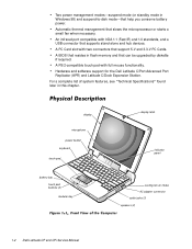
... cooling-fan air intake AC adapter connector audio jacks (3) speakers (2) 1-2 Dell Latitude CP and CPi Service Manual Automatic thermal management that can be upgraded by diskette if required. A BIOS that resides in this chapter. For a complete list of system features, see "Technical Specifications" found later in flash memory and that slows the microprocessor or...
... cooling-fan air intake AC adapter connector audio jacks (3) speakers (2) 1-2 Dell Latitude CP and CPi Service Manual Automatic thermal management that can be upgraded by diskette if required. A BIOS that resides in this chapter. For a complete list of system features, see "Technical Specifications" found later in flash memory and that slows the microprocessor or...
Service Manual
Page 35
... board faulty. The diagnostics contains tests that aid in RTC does not match system clock. If needed, see Chapter 4, "Running the Dell Diagnostics," in protected mode Warning! Tests the video subsystem Keyboard - Tests the mouse/touch-pad subsystem Diskette Drives - hard-disk drive...Serial/Infrared Ports - Seek error Shutdown failure Time-of-day clock lost its charge. Microprocessor unable to find Defective diskette or specific track on system board malfunctioning. Reserve battery lost its charge. Reserve battery lost power MS-DOS unable to System board faulty....
... board faulty. The diagnostics contains tests that aid in RTC does not match system clock. If needed, see Chapter 4, "Running the Dell Diagnostics," in protected mode Warning! Tests the video subsystem Keyboard - Tests the mouse/touch-pad subsystem Diskette Drives - hard-disk drive...Serial/Infrared Ports - Seek error Shutdown failure Time-of-day clock lost its charge. Microprocessor unable to find Defective diskette or specific track on system board malfunctioning. Reserve battery lost its charge. Reserve battery lost power MS-DOS unable to System board faulty....
Service Manual
Page 36
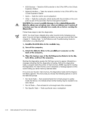
... Run All Tests - Tests a particular area or subsystem 3-10 Dell Latitude CP and CPi Service Manual NOTE: You must have a diskette-drive cable, you which works with the air intake on the computer as part of the computer Run Specific Tests - See Chapter 5, "Getting Help," in the C/Port ...tests the portion of main memory (RAM) required for a thorough test of the automatic thermal management system. Starting the diagnostics causes the Dell logo screen to start the diagnostics. Tests the network controller in main memory, the diagnostics loads and the Diagnostics Menu appears. If no ...
... Run All Tests - Tests a particular area or subsystem 3-10 Dell Latitude CP and CPi Service Manual NOTE: You must have a diskette-drive cable, you which works with the air intake on the computer as part of the computer Run Specific Tests - See Chapter 5, "Getting Help," in the C/Port ...tests the portion of main memory (RAM) required for a thorough test of the automatic thermal management system. Starting the diagnostics causes the Dell logo screen to start the diagnostics. Tests the network controller in main memory, the diagnostics loads and the Diagnostics Menu appears. If no ...

Service Manual
Page 91
screw identification and tightening, 4-3 sockets memory module, 4-17 speakers removal, 4-47 specifications technical, 1-7 subsystems testing, 3-9 system features, 1-1 illustrated, 1-2 system board assembly removal, 4-48 system error messages about, 3-5 list of, 3-5 travel module removal, 4-42 ... routine interpretation, 2-4 external visual inspection, 2-2 initial user contact, 2-1 resource conflicts, eliminating, 2-6 user contact initial, 2-1 visual inspection external, 2-2 ZIF connectors, 4-4 technical specifications, 1-7 tools required, 4-2 touch-pad interface module removal, 4-23 Index 3
screw identification and tightening, 4-3 sockets memory module, 4-17 speakers removal, 4-47 specifications technical, 1-7 subsystems testing, 3-9 system features, 1-1 illustrated, 1-2 system board assembly removal, 4-48 system error messages about, 3-5 list of, 3-5 travel module removal, 4-42 ... routine interpretation, 2-4 external visual inspection, 2-2 initial user contact, 2-1 resource conflicts, eliminating, 2-6 user contact initial, 2-1 visual inspection external, 2-2 ZIF connectors, 4-4 technical specifications, 1-7 tools required, 4-2 touch-pad interface module removal, 4-23 Index 3
Setup Guide
Page 5
...to step 9. 3. Click Change. 7. In the Network window, click the Adapters tab. 12. Type c:\drvlib\netcard\x86\3c90x and click OK. 15. Dell Latitude CP Before You Turn On Your Computer 1-3 Undock the computer. 2. In the Copy the manufacturer's files from box, type a:\ and click OK. 8. If... NIC Diagnostics window, click OK. 21. Click Have Disk. 8. From the menu, select Properties. 11. After the driver is installed in a specific DMA channel. If necessary, see "Installing a Windows NT Driver for the SCSI controller on the C/Dock Expansion Station. SCSI Controller Driver If your...
...to step 9. 3. Click Change. 7. In the Network window, click the Adapters tab. 12. Type c:\drvlib\netcard\x86\3c90x and click OK. 15. Dell Latitude CP Before You Turn On Your Computer 1-3 Undock the computer. 2. In the Copy the manufacturer's files from box, type a:\ and click OK. 8. If... NIC Diagnostics window, click OK. 21. Click Have Disk. 8. From the menu, select Properties. 11. After the driver is installed in a specific DMA channel. If necessary, see "Installing a Windows NT Driver for the SCSI controller on the C/Dock Expansion Station. SCSI Controller Driver If your...


