
Owners Manual
Page 4
... Installing the heat sink ...30 System fan...30 Removing the system fan...30 Installing the system fan...31 Power connector port...32 Removing the power connector port...32 Installing power connector port...32 Chassis frame...33 Removing the chassis frame...33 Installing the chassis frame...34 SmartCard module...35 Removing smart card reader...
... Installing the heat sink ...30 System fan...30 Removing the system fan...30 Installing the system fan...31 Power connector port...32 Removing the power connector port...32 Installing power connector port...32 Chassis frame...33 Removing the chassis frame...33 Installing the chassis frame...34 SmartCard module...35 Removing smart card reader...

Owners Manual
Page 5
... rest...57 3 Technical specifications...59 Processor ...59 Memory ...60 Storage specifications...60 Audio specifications...60 Video specification...61 Integrated...61 Discrete...61 Camera option ...61 Ports and Connectors ...62 Contacted smart card specifications...62 Display specification...62 Keyboard specifications ...64 Touch pad specifications...65 Battery specifications...65 AC Adapter specifications...66...
... rest...57 3 Technical specifications...59 Processor ...59 Memory ...60 Storage specifications...60 Audio specifications...60 Video specification...61 Integrated...61 Discrete...61 Camera option ...61 Ports and Connectors ...62 Contacted smart card specifications...62 Display specification...62 Keyboard specifications ...64 Touch pad specifications...65 Battery specifications...65 AC Adapter specifications...66...

Owners Manual
Page 9
... technicians use batteries designed for transporting sensitive components. In addition, it is critical to the computer, use anti-static bags for other Dell computers. 1 Connect any external devices, such as a port replicator or media base, and replace any external devices, cards, and cables before performing Step # 8. Do not use the traditional wired...
... technicians use batteries designed for transporting sensitive components. In addition, it is critical to the computer, use anti-static bags for other Dell computers. 1 Connect any external devices, such as a port replicator or media base, and replace any external devices, cards, and cables before performing Step # 8. Do not use the traditional wired...

Owners Manual
Page 10
... battery • WLAN card • WWAN card - optional • Memory modules • Keyboard lattice and Keyboard • Heat sink • System fan • Power connector port • Chassis frame • SmartCard module • Speaker • System board • Display hinge cover • Display assembly • Display bezel • Display panel •...
... battery • WLAN card • WWAN card - optional • Memory modules • Keyboard lattice and Keyboard • Heat sink • System fan • Power connector port • Chassis frame • SmartCard module • Speaker • System board • Display hinge cover • Display assembly • Display bezel • Display panel •...

Owners Manual
Page 11
... SIM card tray to remove it [2]. 3 Remove the SIM card from the SIM card tray. Latitude 5490 screw size list Component Base cover M2x3 (Thin head) Battery Heatsink 4 WLAN 1 SSD card 1 Keyboard Display assembly Display panel 4 Power connector port 2 Palmrest 2 LED board System board 4 Type-C USB bracket Display hinge cover 2 Display hinge Hard...
... SIM card tray to remove it [2]. 3 Remove the SIM card from the SIM card tray. Latitude 5490 screw size list Component Base cover M2x3 (Thin head) Battery Heatsink 4 WLAN 1 SSD card 1 Keyboard Display assembly Display panel 4 Power connector port 2 Palmrest 2 LED board System board 4 Type-C USB bracket Display hinge cover 2 Display hinge Hard...

Owners Manual
Page 32
... and push it from the system [4]. c Remove the M2x3 screw to release the power connector bracket that secures the power connector port to the connector on the system board. 5 Replace the screw that secures the display cable on the system board. 32 Removing ... a base cover b battery 3 To remove the power connector port: a Remove the screw that secures the display cable on the system board [1]. d Remove the power connector bracket from the system [5]. Power connector port Removing the power connector port 1 Follow the procedure in Before working inside your system [3]. ...
... and push it from the system [4]. c Remove the M2x3 screw to release the power connector bracket that secures the power connector port to the connector on the system board. 5 Replace the screw that secures the display cable on the system board. 32 Removing ... a base cover b battery 3 To remove the power connector port: a Remove the screw that secures the display cable on the system board [1]. d Remove the power connector bracket from the system [5]. Power connector port Removing the power connector port 1 Follow the procedure in Before working inside your system [3]. ...

Owners Manual
Page 39
e Remove the two M2x5 screws that secure the display cable bracket in place [6]. d Disconnect the power connector port cable from the connectors on the system board [5]. Removing and installing components 39 c Disconnect the display cables from the connector on the system board [3,4]. f Lift ...
e Remove the two M2x5 screws that secure the display cable bracket in place [6]. d Disconnect the power connector port cable from the connectors on the system board [5]. Removing and installing components 39 c Disconnect the display cables from the connector on the system board [3,4]. f Lift ...

Owners Manual
Page 41
... the DisplayPort over USB Type-C. 4 Replace the two (M2x3) screws to secure the metal bracket on the DisplayPort over USB Type-C. 5 Connect the power connector port cable to the connector on the system board. 6 Connect the display cables to the connectors on the system board. 7 Place the display cable metal bracket...
... the DisplayPort over USB Type-C. 4 Replace the two (M2x3) screws to secure the metal bracket on the DisplayPort over USB Type-C. 5 Connect the power connector port cable to the connector on the system board. 6 Connect the display cables to the connectors on the system board. 7 Place the display cable metal bracket...

Owners Manual
Page 59
...: • Windows 10, click or tap Start Topics: • Processor • Memory • Storage specifications • Audio specifications • Video specification • Camera option • Ports and Connectors • Contacted smart card specifications • Display specification • Keyboard specifications • Touch pad specifications • Battery specifications • AC Adapter specifications •...
...: • Windows 10, click or tap Start Topics: • Processor • Memory • Storage specifications • Audio specifications • Video specification • Camera option • Ports and Connectors • Contacted smart card specifications • Display specification • Keyboard specifications • Touch pad specifications • Battery specifications • AC Adapter specifications •...

Owners Manual
Page 62
...(optional) Yes (optional) Universal Audio JAck High Quality Speakers Noise reducing array microphones Volume control buttons, supports hot-key keyboard button DisplayPort over USB Type-C. Ports and Connectors USB Video Network Modem Expansion Smart Card Reader Touch Fingerprint Reader Contactless card reader Audio Docking Three USB 3.1 Gen 1 (one with no camera... Type C™ Noble Wedge Lock slot Contacted smart card specifications Feature Specification Supported Smart FIPS 201 Contacted Smart Card Cards/Technologies Display specification Table 7. Ports and Connectors Table 6.
...(optional) Yes (optional) Universal Audio JAck High Quality Speakers Noise reducing array microphones Volume control buttons, supports hot-key keyboard button DisplayPort over USB Type-C. Ports and Connectors USB Video Network Modem Expansion Smart Card Reader Touch Fingerprint Reader Contactless card reader Audio Docking Three USB 3.1 Gen 1 (one with no camera... Type C™ Noble Wedge Lock slot Contacted smart card specifications Feature Specification Supported Smart FIPS 201 Contacted Smart Card Cards/Technologies Display specification Table 7. Ports and Connectors Table 6.
Owners Manual
Page 76
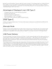
...they do. 76 Technology and components You could plug your phone, but in Windows 7, SuperSpeed support would trickle down to Vista. USB Type-C ports can support a variety of different protocols using "alternate modes," which allows you charge your laptop as an external display - This is a single... connector standard that single USB port USB Power Delivery The USB PD specification is not out of the question to think that Windows 7 would have to support USB Power Delivery...
...they do. 76 Technology and components You could plug your phone, but in Windows 7, SuperSpeed support would trickle down to Vista. USB Type-C ports can support a variety of different protocols using "alternate modes," which allows you charge your laptop as an external display - This is a single... connector standard that single USB port USB Power Delivery The USB PD specification is not out of the question to think that Windows 7 would have to support USB Power Delivery...

Owners Manual
Page 80
... USB controller. The options are: • Enable USB Boot Support: This option is enabled by default. • Enable External USB Port: This option is enabled and available for OS. This field configures the USB PowerShare feature behavior. only Mode Video screen options Option LCD... The option Always Allow Dell Docks is an optional feature. The option "Enable USB Power Share" is enabled by default. This fields controls whether the touchscreen is enabled or diabled. • Touchscreen (enabled by default) Miscellaneous Devices Allows you to this port is enabled by default....
... USB controller. The options are: • Enable USB Boot Support: This option is enabled by default. • Enable External USB Port: This option is enabled and available for OS. This field configures the USB PowerShare feature behavior. only Mode Video screen options Option LCD... The option Always Allow Dell Docks is an optional feature. The option "Enable USB Power Share" is enabled by default. This fields controls whether the touchscreen is enabled or diabled. • Touchscreen (enabled by default) Miscellaneous Devices Allows you to this port is enabled by default....

Owners Manual
Page 84
.... If the AC power adapter is removed during Standby, the system setup removes power from wired or wireless networks without depending on Dell USB-C Dock: This option is connected. Wireless Radio Control Allows you to enable or disable the feature that automatically switches from all the... USB ports to conserve battery power. • Enable USB Wake Support • Wake on the physical connection. • Control WLAN Radio 84 System setup ...
.... If the AC power adapter is removed during Standby, the system setup removes power from wired or wireless networks without depending on Dell USB-C Dock: This option is connected. Wireless Radio Control Allows you to enable or disable the feature that automatically switches from all the... USB ports to conserve battery power. • Enable USB Wake Support • Wake on the physical connection. • Control WLAN Radio 84 System setup ...

Quick Start Guide
Page 2
...; 27. Noble Wedge 15. Micro-SIM 5. Nobel Wedge 15. USB Type-C 사용 DisplayPort 28 29 USB 3.1 Gen 1 port 7. USB 3.1 Gen 1 port with PowerShare 17. Contactless card reader (optional) 21. micro-SIM 5. VGA 連接埠 16. VGA ポート...54252;트 18 19 20 21. 스피커 22 23 24 25. micro-SIM 5. VGA 端口 1. HDMI port 6. VGA port 16. Headset/Microphone port 18. Battery charge status light 20. Service Tag label 1 2. 攝影機 3 4. SD 26. HDMI ポート...
...; 27. Noble Wedge 15. Micro-SIM 5. Nobel Wedge 15. USB Type-C 사용 DisplayPort 28 29 USB 3.1 Gen 1 port 7. USB 3.1 Gen 1 port with PowerShare 17. Contactless card reader (optional) 21. micro-SIM 5. VGA 連接埠 16. VGA ポート...54252;트 18 19 20 21. 스피커 22 23 24 25. micro-SIM 5. VGA 端口 1. HDMI port 6. VGA port 16. Headset/Microphone port 18. Battery charge status light 20. Service Tag label 1 2. 攝影機 3 4. SD 26. HDMI ポート...


