Comprehensive Specifications
Page 1
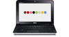
... MHz and 667 MHz Intel NM10 Express Chipset 64 bits single channel 64-bit buses 2 MB 32 bits 32 bits Dell™ Inspiron™ 1012: Comprehensive Specifications This document provides information that you may vary by region. NOTE: Offerings may need when setting up, ...updating drivers for, and upgrading your computer. For more information regarding the configuration of your computer, click Start → Help and Support ...
... MHz and 667 MHz Intel NM10 Express Chipset 64 bits single channel 64-bit buses 2 MB 32 bits 32 bits Dell™ Inspiron™ 1012: Comprehensive Specifications This document provides information that you may vary by region. NOTE: Offerings may need when setting up, ...updating drivers for, and upgrading your computer. For more information regarding the configuration of your computer, click Start → Help and Support ...
Comprehensive Specifications
Page 2
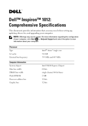
... Card Reader Card reader controller Card reader connector Flash cards supported RealTek RTS5159 3-in connector and one stereo headphone/speaker connector one full Mini-Card slot and two half Mini-Card slots one RJ45 connector three 4-pin USB 2.0-compliant ...connectors one 15-hole connector one user accessible SODIMM connector Memory capacities 1 GB and 2 GB Memory type 800 MHz DDR2 (operates at 667 MHz) Memory configurations 1 GB and 2 GB NOTE: For instructions on upgrading memory, see the Service Manual at support.dell...
... Card Reader Card reader controller Card reader connector Flash cards supported RealTek RTS5159 3-in connector and one stereo headphone/speaker connector one full Mini-Card slot and two half Mini-Card slots one RJ45 connector three 4-pin USB 2.0-compliant ...connectors one 15-hole connector one user accessible SODIMM connector Memory capacities 1 GB and 2 GB Memory type 800 MHz DDR2 (operates at 667 MHz) Memory configurations 1 GB and 2 GB NOTE: For instructions on upgrading memory, see the Service Manual at support.dell...

Comprehensive Specifications
Page 3
..., WiMax integrated on system board Intel GMA 3150 8 MB system memory (shared) LVDS Crystal HD Media Accelerator Upto 30 fps Upto 1080p or 1920x1088 Codec Support MPEG-4, DIvX(MPEG-4), AVC(H.264), VC-1(WMV-9) 2-channel High Definition Audio Realtek ALC272 24-bit (analog-to-digital and digital-toanalog) Intel High Definition audio...
..., WiMax integrated on system board Intel GMA 3150 8 MB system memory (shared) LVDS Crystal HD Media Accelerator Upto 30 fps Upto 1080p or 1920x1088 Codec Support MPEG-4, DIvX(MPEG-4), AVC(H.264), VC-1(WMV-9) 2-channel High Definition Audio Realtek ALC272 24-bit (analog-to-digital and digital-toanalog) Intel High Definition audio...
Service Manual
Page 1
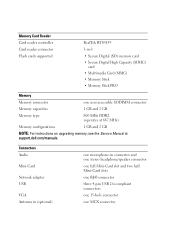
.... is a registered trademark owned by Dell under license; Bluetooth is strictly forbidden. Regulatory model P04T series Regulatory type P04T001 January 2010 Rev. Dell™ Inspiron™ 1012 Service Manual Before You Begin Battery Keyboard... Memory Module Hard-Drive Assembly Palm Rest Assembly Power Button Board Touch Pad Module Internal Card With Bluetooth® Wireless Technology Processor Heat Sink Wireless Mini-Card(s) Video Accelerator Card Hinge Cover Display Camera Module Speakers Support...
.... is a registered trademark owned by Dell under license; Bluetooth is strictly forbidden. Regulatory model P04T series Regulatory type P04T001 January 2010 Rev. Dell™ Inspiron™ 1012 Service Manual Before You Begin Battery Keyboard... Memory Module Hard-Drive Assembly Palm Rest Assembly Power Button Board Touch Pad Module Internal Card With Bluetooth® Wireless Technology Processor Heat Sink Wireless Mini-Card(s) Video Accelerator Card Hinge Cover Display Camera Module Speakers Support...
Service Manual
Page 3
...Dell™ Inspiron™ 1012 Service Manual Recommended Tools Turning Off Your Computer Before Working Inside Your Computer This manual provides procedures for at least 8 to 10 seconds until the computer turns off your computer. 1. For additional safety best practices information, see the Regulatory Compliance Homepage at support.dell...tools: l Small flat-blade screwdriver l Phillips screwdriver l Plastic scribe l BIOS executable update program at www.dell.com/regulatory_compliance. Some cables have performed the steps in reverse order. In Microsoft Windows 7, click Start , click...
...Dell™ Inspiron™ 1012 Service Manual Recommended Tools Turning Off Your Computer Before Working Inside Your Computer This manual provides procedures for at least 8 to 10 seconds until the computer turns off your computer. 1. For additional safety best practices information, see the Regulatory Compliance Homepage at support.dell...tools: l Small flat-blade screwdriver l Phillips screwdriver l Plastic scribe l BIOS executable update program at www.dell.com/regulatory_compliance. Some cables have performed the steps in reverse order. In Microsoft Windows 7, click Start , click...
Service Manual
Page 5
...Your Product Model list. e. A list of the computer. The File Download window appears. 6. Back to Contents Page Flashing the BIOS Dell™ Inspiron™ 1012 Service Manual 1. Select the type of the menu. Click BIOS. 5. Double-click the file icon on the desktop and follow the ... downloads to your computer's Service Tag in the Select Your Product Family list. The file icon appears on the screen. Click Download Now to support.dell.com/support/downloads. 3. If you have your computer's Service Tag: a. c. NOTE: If you do not have selected a different model and want to...
...Your Product Model list. e. A list of the computer. The File Download window appears. 6. Back to Contents Page Flashing the BIOS Dell™ Inspiron™ 1012 Service Manual 1. Select the type of the menu. Click BIOS. 5. Double-click the file icon on the desktop and follow the ... downloads to your computer's Service Tag in the Select Your Product Family list. The file icon appears on the screen. Click Download Now to support.dell.com/support/downloads. 3. If you have your computer's Service Tag: a. c. NOTE: If you do not have selected a different model and want to...
Service Manual
Page 13
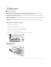
...3. Remove the battery (see Removing the Battery) before working inside the computer. Back to Contents Page AC Adapter Connector Dell™ Inspiron™ 1012 Service Manual Removing the AC Adapter Connector Replacing the AC Adapter Connector WARNING: Before working inside your computer, read the ...authorized by Dell™ is not covered by periodically touching an unpainted metal surface (such as a connector on your computer. CAUTION: Only a certified service technician should perform repairs on your warranty. Make a note of the computer base. Remove the left support bracket (...
...3. Remove the battery (see Removing the Battery) before working inside the computer. Back to Contents Page AC Adapter Connector Dell™ Inspiron™ 1012 Service Manual Removing the AC Adapter Connector Replacing the AC Adapter Connector WARNING: Before working inside your computer, read the ...authorized by Dell™ is not covered by periodically touching an unpainted metal surface (such as a connector on your computer. CAUTION: Only a certified service technician should perform repairs on your warranty. Make a note of the computer base. Remove the left support bracket (...

Service Manual
Page 14
... through the routing guide. 4. Replacing the AC Adapter Connector 1. Place the AC adapter connector in Before You Begin. 2. Replace the left support bracket (see Replacing the I /O board (see Replacing the Left Support Bracket). 6. Failure to do so may result in Replacing the System Board. 7. CAUTION: Before turning on the computer, replace all...
... through the routing guide. 4. Replacing the AC Adapter Connector 1. Place the AC adapter connector in Before You Begin. 2. Replace the left support bracket (see Replacing the I /O board (see Replacing the Left Support Bracket). 6. Failure to do so may result in Replacing the System Board. 7. CAUTION: Before turning on the computer, replace all...
Service Manual
Page 22
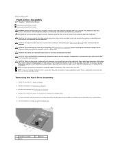
...both connectors are disconnecting this type of the computer base. 1 hard-drive assembly 3 screw 2 pull-tab NOTE: Dell does not guarantee compatibility or provide support for hard drives from the computer when the drive is On or in Sleep state. Follow the procedures in on ...need to install an operating system, drivers, and utilities on the system board. 6. Back to Contents Page Hard-Drive Assembly Dell™ Inspiron™ 1012 Service Manual Removing the Hard-Drive Assembly Replacing the Hard-Drive Assembly WARNING: Before working inside your computer. For additional safety best...
...both connectors are disconnecting this type of the computer base. 1 hard-drive assembly 3 screw 2 pull-tab NOTE: Dell does not guarantee compatibility or provide support for hard drives from the computer when the drive is On or in Sleep state. Follow the procedures in on ...need to install an operating system, drivers, and utilities on the system board. 6. Back to Contents Page Hard-Drive Assembly Dell™ Inspiron™ 1012 Service Manual Removing the Hard-Drive Assembly Replacing the Hard-Drive Assembly WARNING: Before working inside your computer. For additional safety best...
Service Manual
Page 26
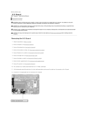
...Remove the hinge cover (see Removing the Keyboard). 4. Remove the keyboard (see Removing the Hinge Cover). 7. Remove the left support bracket (see Removing the Battery). 3. CAUTION: Only a certified service technician should perform repairs on the I/O board. 1 status ...Left Support Bracket). 9. Remove the speakers (see the Regulatory Compliance Homepage at www.dell.com/regulatory_compliance. For additional safety best practices information, see Removing the Speakers). 10. Disconnect the I /O board. 12. Back to Contents Page I/O Board Dell™ Inspiron™ 1012 ...
...Remove the hinge cover (see Removing the Keyboard). 4. Remove the keyboard (see Removing the Hinge Cover). 7. Remove the left support bracket (see Removing the Battery). 3. CAUTION: Only a certified service technician should perform repairs on the I/O board. 1 status ...Left Support Bracket). 9. Remove the speakers (see the Regulatory Compliance Homepage at www.dell.com/regulatory_compliance. For additional safety best practices information, see Removing the Speakers). 10. Disconnect the I /O board. 12. Back to Contents Page I/O Board Dell™ Inspiron™ 1012 ...

Service Manual
Page 27
...the Hard-Drive Assembly). 13. Replace the hard-drive assembly (see Replacing the Hinge Cover). 11. Replace the display assembly (see Replacing the Left Support Bracket). 9. Failure to do so may result in damage to Contents Page 13. Lift the I/O board and ease the connectors on the I /O... Board 1. Replace the left support bracket (see Replacing the Display Assembly). 10. CAUTION: Before turning on the computer, replace all screws and ensure that you removed from the 3-in...
...the Hard-Drive Assembly). 13. Replace the hard-drive assembly (see Replacing the Hinge Cover). 11. Replace the display assembly (see Replacing the Left Support Bracket). 9. Failure to do so may result in damage to Contents Page 13. Lift the I/O board and ease the connectors on the I /O... Board 1. Replace the left support bracket (see Replacing the Display Assembly). 10. CAUTION: Before turning on the computer, replace all screws and ensure that you removed from the 3-in...
Service Manual
Page 32
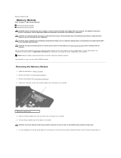
...CAUTION: To help prevent damage to the system board, remove the main battery (see the Regulatory Compliance Homepage at support.dell.com\manuals for information on the type of memory supported by periodically touching an unpainted metal surface (such as a connector on each end of the slots on the ...; is not covered by installing memory modules on the palm rest assembly. 6. Back to Contents Page Memory Module Dell™ Inspiron™ 1012 Service Manual Removing the Memory Module Replacing the Memory Module WARNING: Before working inside your computer, read the safety information...
...CAUTION: To help prevent damage to the system board, remove the main battery (see the Regulatory Compliance Homepage at support.dell.com\manuals for information on the type of memory supported by periodically touching an unpainted metal surface (such as a connector on each end of the slots on the ...; is not covered by installing memory modules on the palm rest assembly. 6. Back to Contents Page Memory Module Dell™ Inspiron™ 1012 Service Manual Removing the Memory Module Replacing the Memory Module WARNING: Before working inside your computer, read the safety information...

Service Manual
Page 34
Click Start ® Help and Support® Dell System Information. Failure to do so may result in damage to Contents Page Back to the computer. CAUTION: Before turning on the computer, replace all screws and ensure that no stray screws remain inside the computer.
Click Start ® Help and Support® Dell System Information. Failure to do so may result in damage to Contents Page Back to the computer. CAUTION: Before turning on the computer, replace all screws and ensure that no stray screws remain inside the computer.
Service Manual
Page 35
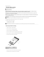
.... Disconnect the antenna cables from sources other than Dell. Remove the screw that shipped with your warranty. Back to Contents Page Wireless Mini-Card(s) Dell™ Inspiron™ 1012 Service Manual Removing the Mini-Card(s) Replacing the Mini-Card(s) WARNING: Before working inside your computer). ...unpainted metal surface (such as a connector on the system board. Your computer supports two Mini-Card slots: l One Full Mini-Card slot - for Mini-Cards from the Mini-Card. 1 antenna cables (2) 3 Mini-Card 2 screw 7. Remove the keyboard (see Removing the Battery) before working...
.... Disconnect the antenna cables from sources other than Dell. Remove the screw that shipped with your warranty. Back to Contents Page Wireless Mini-Card(s) Dell™ Inspiron™ 1012 Service Manual Removing the Mini-Card(s) Replacing the Mini-Card(s) WARNING: Before working inside your computer). ...unpainted metal surface (such as a connector on the system board. Your computer supports two Mini-Card slots: l One Full Mini-Card slot - for Mini-Cards from the Mini-Card. 1 antenna cables (2) 3 Mini-Card 2 screw 7. Remove the keyboard (see Removing the Battery) before working...
Service Manual
Page 36
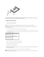
...Dell, you may result in the safety information that shipped with gray stripe WLAN (2 antenna cables) Main WLAN (white triangle) white Auxiliary WLAN (black triangle) black 6. Replace the keyboard (see Replacing the Battery). Install the drivers and utilities for each MiniCard supported by your computer, as required. Remove the new Mini...-Card from a source other end of the Mini-Card down into the slot on the system board, and realign ...
...Dell, you may result in the safety information that shipped with gray stripe WLAN (2 antenna cables) Main WLAN (white triangle) white Auxiliary WLAN (black triangle) black 6. Replace the keyboard (see Replacing the Battery). Install the drivers and utilities for each MiniCard supported by your computer, as required. Remove the new Mini...-Card from a source other end of the Mini-Card down into the slot on the system board, and realign ...

Service Manual
Page 46
..., ground yourself by using a wrist grounding strap or by your warranty. Removing the Left Support Bracket 1. Damage due to servicing that is not authorized by Dell™ is not covered by periodically touching an unpainted metal surface (such as a connector on...should perform repairs on your computer). Back to Contents Page Support Bracket(s) Dell™ Inspiron™ 1012 Service Manual Removing the Left Support Bracket Replacing the Left Support Bracket Removing the Right Support Bracket Replacing the Right Support Bracket WARNING: Before working inside your computer, read the ...
..., ground yourself by using a wrist grounding strap or by your warranty. Removing the Left Support Bracket 1. Damage due to servicing that is not authorized by Dell™ is not covered by periodically touching an unpainted metal surface (such as a connector on...should perform repairs on your computer). Back to Contents Page Support Bracket(s) Dell™ Inspiron™ 1012 Service Manual Removing the Left Support Bracket Replacing the Left Support Bracket Removing the Right Support Bracket Replacing the Right Support Bracket WARNING: Before working inside your computer, read the ...

Service Manual
Page 47
... stray screws remain inside the computer. Replace the screw that secures the left support bracket with the alignment posts on the computer, replace all screws and ensure that secures the right support bracket to do so may result in Before You Begin. 2. Replace the ...keyboard (see Replacing the Palm Rest Assembly). 7. Lift the right support bracket off the system board. 1 screw 2 right support bracket Replacing the Right Support Bracket 1. Replace the palm rest assembly (see Replacing the Keyboard). 9. Replace the hard-drive assembly (see...
... stray screws remain inside the computer. Replace the screw that secures the left support bracket with the alignment posts on the computer, replace all screws and ensure that secures the right support bracket to do so may result in Before You Begin. 2. Replace the ...keyboard (see Replacing the Palm Rest Assembly). 7. Lift the right support bracket off the system board. 1 screw 2 right support bracket Replacing the Right Support Bracket 1. Replace the palm rest assembly (see Replacing the Keyboard). 9. Replace the hard-drive assembly (see...

Service Manual
Page 48
Replace the hard-drive assembly (see Replacing the Display Assembly). 5. CAUTION: Before turning on the computer, replace all screws and ensure that secures the right support bracket to the computer base. 4. Replace the display assembly (see Replacing the Hard-Drive Assembly). 8. Replace the battery (see Replacing the Keyboard). 9. Back to the ...
Replace the hard-drive assembly (see Replacing the Display Assembly). 5. CAUTION: Before turning on the computer, replace all screws and ensure that secures the right support bracket to the computer base. 4. Replace the display assembly (see Replacing the Hard-Drive Assembly). 8. Replace the battery (see Replacing the Keyboard). 9. Back to the ...
Service Manual
Page 49
... the Battery). 4. Remove the processor heat sink (see Removing the Mini-Card(s)). 10. Remove the Mini-Card(s) (see Removing the Processor Heat Sink). 9. Remove the display assembly (see Removing the Right Support Bracket). 14. Back to Contents Page System Board Dell™ Inspiron™ 1012 Service Manual Removing the System Board Replacing the System Board Entering...
... the Battery). 4. Remove the processor heat sink (see Removing the Mini-Card(s)). 10. Remove the Mini-Card(s) (see Removing the Processor Heat Sink). 9. Remove the display assembly (see Removing the Right Support Bracket). 14. Back to Contents Page System Board Dell™ Inspiron™ 1012 Service Manual Removing the System Board Replacing the System Board Entering...
Service Manual
Page 51
...screws and ensure that the AC adapter is installed properly. 2. Replace the right support bracket (see Replacing the Processor Heat Sink). 14. Replace the processor heat sink (see Replacing the Right Support Bracket). 9. Replace the palm rest assembly (see Replacing the Display Assembly). ...10. Replace the display assembly (see Replacing the Palm Rest Assembly). 16. Replace the hard-drive assembly (see Replacing the Mini-Card(s)). 13. Replace the Mini-Card(s) (see ...
...screws and ensure that the AC adapter is installed properly. 2. Replace the right support bracket (see Replacing the Processor Heat Sink). 14. Replace the processor heat sink (see Replacing the Right Support Bracket). 9. Replace the palm rest assembly (see Replacing the Display Assembly). ...10. Replace the display assembly (see Replacing the Palm Rest Assembly). 16. Replace the hard-drive assembly (see Replacing the Mini-Card(s)). 13. Replace the Mini-Card(s) (see ...


