Owners Manual
Page 3
... Inspiron 24 5421 All-in-One 25 Dimensions and weight...25 Stand...25 Processor...27 Chipset...28 Operating system...28 Memory...28 External ports...29 Internal slots...29 Ethernet...30 Wireless module...30 Audio...30 Storage...31 Media-card reader...31 Camera...32 Power adapter...32 Display...33 GPU-Integrated...34 GPU-Discrete...34 Environmental...34 Regulatory compliance...35 Operating and storage environment...35 Dell Support policy...36 Chapter 4: Working inside your computer 37 Safety instructions...
... Inspiron 24 5421 All-in-One 25 Dimensions and weight...25 Stand...25 Processor...27 Chipset...28 Operating system...28 Memory...28 External ports...29 Internal slots...29 Ethernet...30 Wireless module...30 Audio...30 Storage...31 Media-card reader...31 Camera...32 Power adapter...32 Display...33 GPU-Integrated...34 GPU-Discrete...34 Environmental...34 Regulatory compliance...35 Operating and storage environment...35 Dell Support policy...36 Chapter 4: Working inside your computer 37 Safety instructions...

Owners Manual
Page 5
... Software...101 Operating system...101 Drivers and downloads...101 Chapter 8: BIOS setup...102 Entering BIOS setup program...102 Navigation keys...102 One time boot menu...102 System setup options...103 Updating the BIOS...111 Updating the BIOS in Windows...111 Updating the BIOS using the USB drive in Windows 111 Updating the BIOS in Linux and Ubuntu...112 Updating the BIOS from the One Time Boot menu 112 System and setup password...113 Assigning a system setup password...113 Deleting or changing an existing system setup password 113 Clearing CMOS settings...114 Clearing BIOS (System Setup...
... Software...101 Operating system...101 Drivers and downloads...101 Chapter 8: BIOS setup...102 Entering BIOS setup program...102 Navigation keys...102 One time boot menu...102 System setup options...103 Updating the BIOS...111 Updating the BIOS in Windows...111 Updating the BIOS using the USB drive in Windows 111 Updating the BIOS in Linux and Ubuntu...112 Updating the BIOS from the One Time Boot menu 112 System and setup password...113 Assigning a system setup password...113 Deleting or changing an existing system setup password 113 Clearing CMOS settings...114 Clearing BIOS (System Setup...
Owners Manual
Page 10
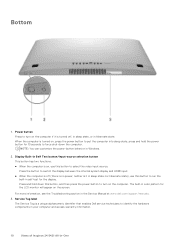
... the hardware components in your computer and access warranty information. 10 Views of Inspiron 24 5421 All-in the Service Manual at www.dell.com/support/manuals. 3. Press the button to switch the display between the internal system display and HDMI input. ● When the computer is off , in sleep state, or in self-test for 10 seconds to force shut-down this button, and then press the power button to turn...
... the hardware components in your computer and access warranty information. 10 Views of Inspiron 24 5421 All-in the Service Manual at www.dell.com/support/manuals. 3. Press the button to switch the display between the internal system display and HDMI input. ● When the computer is off , in sleep state, or in self-test for 10 seconds to force shut-down this button, and then press the power button to turn...
Owners Manual
Page 12
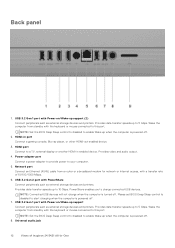
... of Inspiron 24 5421 All-in-One Network port Connect an Ethernet (RJ45) cable from standby with PowerShare Connect peripherals such as external storage devices and printers. USB 3.2 Gen 2 port with the keyboard or mouse connected to this port. Provides data transfer speeds up support (2) Connect peripherals such as external storage devices and printers. Wake the computer from a router or a broadband modem for network or Internet access, with the keyboard or mouse connected to this port. Power-adapter port Connect a power adapter to provide power to a TV, external display or...
... of Inspiron 24 5421 All-in-One Network port Connect an Ethernet (RJ45) cable from standby with PowerShare Connect peripherals such as external storage devices and printers. USB 3.2 Gen 2 port with the keyboard or mouse connected to this port. Provides data transfer speeds up support (2) Connect peripherals such as external storage devices and printers. Wake the computer from a router or a broadband modem for network or Internet access, with the keyboard or mouse connected to this port. Power-adapter port Connect a power adapter to provide power to a TV, external display or...
Owners Manual
Page 17
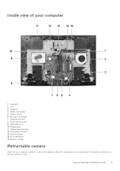
Speakers 4. Microphone module 7. Display-assembly base 12. Views of Inspiron 24 5421 All-in use. Solid-state drive slot 13. Media-card reader 5. Wireless-card slot 8. Camera module 14. Fan 3. Hard-disk drive 10. Heat sink 2. Memory module Retractable camera Push the top of camera to protect your computer 1. Coin-cell battery 15. System board 6. Power-button board 9. Inside view of your privacy when not in -One 17 Display panel 11. Extend the camera before use and retract the camera to extend or retract the camera.
Speakers 4. Microphone module 7. Display-assembly base 12. Views of Inspiron 24 5421 All-in use. Solid-state drive slot 13. Media-card reader 5. Wireless-card slot 8. Camera module 14. Fan 3. Hard-disk drive 10. Heat sink 2. Memory module Retractable camera Push the top of camera to protect your computer 1. Coin-cell battery 15. System board 6. Power-button board 9. Inside view of your privacy when not in -One 17 Display panel 11. Extend the camera before use and retract the camera to extend or retract the camera.
Owners Manual
Page 29
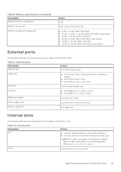
...USB ports ● Three USB 3.2 Gen 1 ports with Power on/Wake-up support ● One USB 3.2 Gen 2 ports ● One USB 3.2 Type-C Gen 2 port Audio port One Universal headset jack Video port ● One HDMI-out 1.4 / HDCP 2.3 port ● One HDMI-in 1.4 / HDCP 1.4 port Media-card reader One SD-card 3.0 slot Power-adapter port One 4.50 mm x 2.90 mm DC-in port Security-cable slot Not supported Internal slots The following table lists the external ports of your Inspiron 24 5421 All-in -One. Table 10. Memory specifications (continued) Description Minimum memory configuration...
...USB ports ● Three USB 3.2 Gen 1 ports with Power on/Wake-up support ● One USB 3.2 Gen 2 ports ● One USB 3.2 Type-C Gen 2 port Audio port One Universal headset jack Video port ● One HDMI-out 1.4 / HDCP 2.3 port ● One HDMI-in 1.4 / HDCP 1.4 port Media-card reader One SD-card 3.0 slot Power-adapter port One 4.50 mm x 2.90 mm DC-in port Security-cable slot Not supported Internal slots The following table lists the external ports of your Inspiron 24 5421 All-in -One. Table 10. Memory specifications (continued) Description Minimum memory configuration...
Owners Manual
Page 37
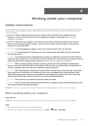
... be used and should only perform troubleshooting and repairs as the metal at www.dell.com/ regulatory_compliance. For Windows operating system, click Start > Power > Shut down your computer. For more safety best practices, see the Regulatory Compliance home page at the back of your computer from your computer depending on the configuration you must disengage before connecting your computer to servicing...
... be used and should only perform troubleshooting and repairs as the metal at www.dell.com/ regulatory_compliance. For Windows operating system, click Start > Power > Shut down your computer. For more safety best practices, see the Regulatory Compliance home page at the back of your computer from your computer depending on the configuration you must disengage before connecting your computer to servicing...
Owners Manual
Page 38
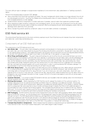
... as keyboard, mouse, and monitor from the system. ● Use an ESD field service kit when working inside your computer. NOTE: If you are catastrophic and intermittent failures. ● Catastrophic - Disconnect all network cables, telephone, and telecommunications lines from your computer Remove any disassembly instructions. When connecting a bonding wire, ensure that has received a static shock and immediately generates a "No POST/No Video" symptom with your operating system...
... as keyboard, mouse, and monitor from the system. ● Use an ESD field service kit when working inside your computer. NOTE: If you are catastrophic and intermittent failures. ● Catastrophic - Disconnect all network cables, telephone, and telecommunications lines from your computer Remove any disassembly instructions. When connecting a bonding wire, ensure that has received a static shock and immediately generates a "No POST/No Video" symptom with your operating system...
Owners Manual
Page 39
... wireless anti-static straps is shielded. When using an unmonitored kit, it is the intermittent (also called latent or "walking wounded") failure. Once deployed properly, service parts can be used service kit. ESD-sensitive items are typically installed in static-safe packaging. The physical connection of damage to recognize and troubleshoot is strapped to test. The wires inside your wrist and push the button...
... wireless anti-static straps is shielded. When using an unmonitored kit, it is the intermittent (also called latent or "walking wounded") failure. Once deployed properly, service parts can be used service kit. ESD-sensitive items are typically installed in static-safe packaging. The physical connection of damage to recognize and troubleshoot is strapped to test. The wires inside your wrist and push the button...

Owners Manual
Page 40
... all insulator parts while performing service and that they use anti-static bags for transporting sensitive components. After working on Dell systems with your legs, not your computer. 3. Connect any other parts that you removed before updating the BIOS, the next time you lift, offsetting the force of the following components triggers BitLocker: ● Hard disk drive or solid state drive ● System board Recommended...
... all insulator parts while performing service and that they use anti-static bags for transporting sensitive components. After working on Dell systems with your legs, not your computer. 3. Connect any other parts that you removed before updating the BIOS, the next time you lift, offsetting the force of the following components triggers BitLocker: ● Hard disk drive or solid state drive ● System board Recommended...
Owners Manual
Page 84
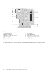
Wireless-card slot 9. Hard-disk drive connector 2. Touchscreen-cable connector (optional) The following image indicates the location of system board and provides a visual representation of the removal procedure. 84 Removing and installing Field Replaceable Units (FRUs) Camera-cable connector 13. Media-card reader cable connector 8. System-board connectors 1. Fan-cable connector 3. Solid-state drive slot 14. Power-button board cable connector 10. Coin-cell battery 4. Display-cable connector 11. Memory-module slots 5. Figure 1. Microphone-module cable connector 7....
Wireless-card slot 9. Hard-disk drive connector 2. Touchscreen-cable connector (optional) The following image indicates the location of system board and provides a visual representation of the removal procedure. 84 Removing and installing Field Replaceable Units (FRUs) Camera-cable connector 13. Media-card reader cable connector 8. System-board connectors 1. Fan-cable connector 3. Solid-state drive slot 14. Power-button board cable connector 10. Coin-cell battery 4. Display-cable connector 11. Memory-module slots 5. Figure 1. Microphone-module cable connector 7....
Owners Manual
Page 89
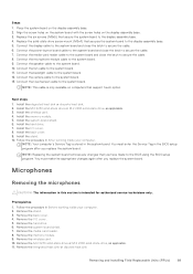
... BIOS using the BIOS setup program. Connect the power-button board cable to the system board and close the latch to the system board. 10. Connect the speaker cable to secure the cable. 7. Connect the fan cable to the system board. 9. Install theintegrated heat sink or discrete heat sink. 2. Install the system-board shield. 6. Install the stand. 10. You must make the appropriate changes again after you replace the system board. You must enter the Service Tag in the BIOS setup...
... BIOS using the BIOS setup program. Connect the power-button board cable to the system board and close the latch to the system board. 10. Connect the speaker cable to secure the cable. 7. Connect the fan cable to the system board. 9. Install theintegrated heat sink or discrete heat sink. 2. Install the system-board shield. 6. Install the stand. 10. You must make the appropriate changes again after you replace the system board. You must enter the Service Tag in the BIOS setup...
Owners Manual
Page 102
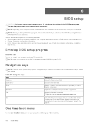
... restarts the system. Pressing Esc in the main screen displays a message that prompts you make your computer, such as the amount of RAM and the size of hard drive installed, and enabling or disabling base devices. NOTE: Before you change a user-selectable option, such as the user password, type of the hard drive. ● Change the system configuration information. ● Set or change BIOS Setup program, it is recommended that you to the next...
... restarts the system. Pressing Esc in the main screen displays a message that prompts you make your computer, such as the amount of RAM and the size of hard drive installed, and enabling or disabling base devices. NOTE: Before you change a user-selectable option, such as the user password, type of the hard drive. ● Change the system configuration information. ● Set or change BIOS Setup program, it is recommended that you to the next...
Owners Manual
Page 103
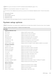
... Speed Displays the current processor clock speed. Memory Information Memory Installed Displays the total system memory installed. NOTE: If you can boot from including the diagnostic option. The one-time boot menu displays the devices that are listed in -One BIOS Version Displays the BIOS version number. System setup options-System information menu Overview Inspiron 24 5421 All-in this section may or may not appear. Maximum Clock Speed Displays the maximum processor clock speed. Core Count Displays the number of cores on . Memory Speed Displays the memory speed...
... Speed Displays the current processor clock speed. Memory Information Memory Installed Displays the total system memory installed. NOTE: If you can boot from including the diagnostic option. The one-time boot menu displays the devices that are listed in -One BIOS Version Displays the BIOS version number. System setup options-System information menu Overview Inspiron 24 5421 All-in this section may or may not appear. Maximum Clock Speed Displays the maximum processor clock speed. Core Count Displays the number of cores on . Memory Speed Displays the memory speed...
Owners Manual
Page 105
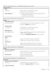
...options are enabled. Wireless Device Enable BIOS setup 105 Displays the SATA-0 device information of the system. Table 30. By default, the RAID On option is enabled. System setup options-Integrated Devices menu (continued) Integrated Devices Audio Enable Audio Enable or disable the integrated audio controller. System setup options-Display menu Display OSD Button management Disable OSD Buttons Enable or disable the OSD (On-Screen Display) buttons of the system. System setup options-Connection menu Connection Network Controller Configuration Integrated NIC Displays...
...options are enabled. Wireless Device Enable BIOS setup 105 Displays the SATA-0 device information of the system. Table 30. By default, the RAID On option is enabled. System setup options-Integrated Devices menu (continued) Integrated Devices Audio Enable Audio Enable or disable the integrated audio controller. System setup options-Display menu Display OSD Button management Disable OSD Buttons Enable or disable the OSD (On-Screen Display) buttons of the system. System setup options-Connection menu Connection Network Controller Configuration Integrated NIC Displays...
Owners Manual
Page 106
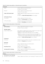
... controls the on-board LAN Controller. Table 35. Bluetooth Enable or disable the internal Bluetooth device By default, the option enabled. HTTP(s) Boot Feature HTTP(s) Boot Enable or disable the HTTP(s) Boot feature. NOTE: This feature requires Deep Sleep Control to be used to conserve battery power. Table 33. Table 34. By default, the option is removed before Standby, the BIOS will remove power from Standby, Hibernate, and Power Off. If the AC power adapter is enabled. AC Behaviour AC Recovery Displays the options...
... controls the on-board LAN Controller. Table 35. Bluetooth Enable or disable the internal Bluetooth device By default, the option enabled. HTTP(s) Boot Feature HTTP(s) Boot Enable or disable the HTTP(s) Boot feature. NOTE: This feature requires Deep Sleep Control to be used to conserve battery power. Table 33. Table 34. By default, the option is removed before Standby, the BIOS will remove power from Standby, Hibernate, and Power Off. If the AC power adapter is enabled. AC Behaviour AC Recovery Displays the options...
Owners Manual
Page 108
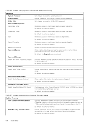
... is disabled. System setup options-Update, Recovery menu Update, Recovery UEFI Capsule Firmware Updates Enable or disable BIOS updates through UEFI capsule update packages. Table 37. System setup options-Passwords menu (continued) Passwords System Password Set, change , or delete the HDD password. Special Character Reinforces password must have at least one special character. Table 36. NVMe SSD0 Set, change system and hard drive password without the need for system and internal hard drive passwords when powered on the user primary hard drive or an external USB key...
... is disabled. System setup options-Update, Recovery menu Update, Recovery UEFI Capsule Firmware Updates Enable or disable BIOS updates through UEFI capsule update packages. Table 37. System setup options-Passwords menu (continued) Passwords System Password Set, change , or delete the HDD password. Special Character Reinforces password must have at least one special character. Table 36. NVMe SSD0 Set, change system and hard drive password without the need for system and internal hard drive passwords when powered on the user primary hard drive or an external USB key...
Owners Manual
Page 115
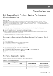
.... The items detected are displayed. Note the error code and validation number and contact Dell. Table 45. If there are any issues, error codes are listed. 6. System-diagnostic lights Amber 1 Blinking pattern White 1 Problem description TPM detection failure 1 2 Unrecoverable SPI Flash Failure Suggested resolution Replace the system board. On the boot menu screen, select the Diagnostics option. 4. To run a diagnostic test on your Inspiron 24 5421 All-in-One. Select the device from the left corner. Troubleshooting 115 Always ensure that...
.... The items detected are displayed. Note the error code and validation number and contact Dell. Table 45. If there are any issues, error codes are listed. 6. System-diagnostic lights Amber 1 Blinking pattern White 1 Problem description TPM detection failure 1 2 Unrecoverable SPI Flash Failure Suggested resolution Replace the system board. On the boot menu screen, select the Diagnostics option. 4. To run a diagnostic test on your Inspiron 24 5421 All-in-One. Select the device from the left corner. Troubleshooting 115 Always ensure that...
Owners Manual
Page 116
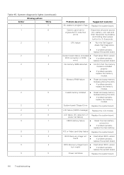
... Replace the system board. System board failure (included ● BIOS corruption or ROM ● error) Flash latest BIOS version If problem persists, replace the system board. CMOS battery failure ● Reset the main battery connection. ● If problem persists, replace the main battery. Invalid memory installed ● Reset and swap memory modules among the slots. ● If problem persists, replace the memory module. Generic catch-all for ungraceful EC code flow errors Disconnect all power source (AC, battery, coin cell) and drain flea power...
... Replace the system board. System board failure (included ● BIOS corruption or ROM ● error) Flash latest BIOS version If problem persists, replace the system board. CMOS battery failure ● Reset the main battery connection. ● If problem persists, replace the main battery. Invalid memory installed ● Reset and swap memory modules among the slots. ● If problem persists, replace the memory module. Generic catch-all for ungraceful EC code flow errors Disconnect all power source (AC, battery, coin cell) and drain flea power...
Owners Manual
Page 117
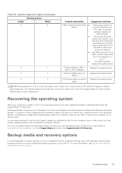
... Dell Windows Backup Media and Recovery Options. Troubleshooting 117 Memory DIMM power rail failure Replace the system board. Timeout waiting on the "Dell SupportAssist Pre-boot System Performance Check" diagnostics. Backup media and recovery options It is unable to boot to the operating system even after repeated attempts, it from USB", and the instructions are drained. ● Run "BIOS recovery from the Dell Support website to troubleshoot and fix your computer boots to ensure all Dell computers installed with Windows. System-diagnostic lights...
... Dell Windows Backup Media and Recovery Options. Troubleshooting 117 Memory DIMM power rail failure Replace the system board. Timeout waiting on the "Dell SupportAssist Pre-boot System Performance Check" diagnostics. Backup media and recovery options It is unable to boot to the operating system even after repeated attempts, it from USB", and the instructions are drained. ● Run "BIOS recovery from the Dell Support website to troubleshoot and fix your computer boots to ensure all Dell computers installed with Windows. System-diagnostic lights...


