Service Manual
Page 4
......61 Removing the display panel...61 Installing the display panel...63 Base panel...65 Removing the base panel...65 Installing the base panel...67 Chapter 3: Drivers and downloads 69 Chapter 4: System setup...70 Entering BIOS setup program...70 Navigation keys...70 Boot Sequence...70 One time boot menu...71 System setup options...71 System and setup password...80 Assigning a system setup password...80 Deleting or changing an existing system setup password 80 Clearing CMOS settings...81 Clearing BIOS (System Setup) and System passwords 81 Updating the BIOS...81 Updating the BIOS in Windows...
......61 Removing the display panel...61 Installing the display panel...63 Base panel...65 Removing the base panel...65 Installing the base panel...67 Chapter 3: Drivers and downloads 69 Chapter 4: System setup...70 Entering BIOS setup program...70 Navigation keys...70 Boot Sequence...70 One time boot menu...71 System setup options...71 System and setup password...80 Assigning a system setup password...80 Deleting or changing an existing system setup password 80 Clearing CMOS settings...81 Clearing BIOS (System Setup) and System passwords 81 Updating the BIOS...81 Updating the BIOS in Windows...
Service Manual
Page 6
... then unplug the cable from all power sources before opening the computer cover or panels. Damage due to servicing that the work , periodically touch an unpainted metal surface to ensure your personal safety. CAUTION: You should only perform troubleshooting and repairs as keyboard, mouse, and monitor from your computer depending on the configuration you disconnect a cable, pull it by your computer. Click Start > Power > Shut down...
... then unplug the cable from all power sources before opening the computer cover or panels. Damage due to servicing that the work , periodically touch an unpainted metal surface to ensure your personal safety. CAUTION: You should only perform troubleshooting and repairs as keyboard, mouse, and monitor from your computer depending on the configuration you disconnect a cable, pull it by your computer. Click Start > Power > Shut down...

Service Manual
Page 7
... device functionality. Perform the following steps to protect hardware that has received a static shock and immediately generates a "No POST/No Video" symptom with a beep code emitted for lower power requirements and increased density, ESD protection is a major concern when you handle electronic components, especially sensitive components such as expansion cards, processors, memory DIMMs, and system boards. If possible, use of handling parts...
... device functionality. Perform the following steps to protect hardware that has received a static shock and immediately generates a "No POST/No Video" symptom with a beep code emitted for lower power requirements and increased density, ESD protection is a major concern when you handle electronic components, especially sensitive components such as expansion cards, processors, memory DIMMs, and system boards. If possible, use of handling parts...

Service Manual
Page 8
... reverse to test. ESD-sensitive devices should always return the damaged part using an unmonitored kit, it is strapped to avoid accidental ESD hardware damage. Always obtain additional resources or use wireless wrist straps. The closer it is being repaired. Follow the same techniques in order to your back. 5. To perform the test, plug the wrist-strap's bonding-wire into the...
... reverse to test. ESD-sensitive devices should always return the damaged part using an unmonitored kit, it is strapped to avoid accidental ESD hardware damage. Always obtain additional resources or use wireless wrist straps. The closer it is being repaired. Follow the same techniques in order to your back. 5. To perform the test, plug the wrist-strap's bonding-wire into the...
Service Manual
Page 9
Replace all attached devices to their electrical outlets. 5. Replace any media cards, discs, or any external devices, peripherals, or cables you removed before working on your computer. Steps 1. Working inside your computer. 2. Connect your computer. Connect any other parts that no stray screws remain inside your computer 9 Turn on your computer and all screws and ensure that you removed before working on your computer. 3. After working inside your computer About this task CAUTION...
Replace all attached devices to their electrical outlets. 5. Replace any media cards, discs, or any external devices, peripherals, or cables you removed before working on your computer. Steps 1. Working inside your computer. 2. Connect your computer. Connect any other parts that no stray screws remain inside your computer 9 Turn on your computer and all screws and ensure that you removed before working on your computer. 3. After working inside your computer About this task CAUTION...

Service Manual
Page 56
... make the appropriate changes again after you replace the system board. Follow the procedure in the system board. Remove the M.2 2230 solid-state drive or M.2 2280 solid-state drive, as applicable. 11. Remove the system-board shield. 7. Microphones Removing the microphones Prerequisites 1. 10. Remove the hard drive. 6. Remove the media-card reader. 8. NOTE: Your computer's Service Tag is stored in Before working inside your computer. Remove the back cover. 4. Remove the system board. You must enter...
... make the appropriate changes again after you replace the system board. Follow the procedure in the system board. Remove the M.2 2230 solid-state drive or M.2 2280 solid-state drive, as applicable. 11. Remove the system-board shield. 7. Microphones Removing the microphones Prerequisites 1. 10. Remove the hard drive. 6. Remove the media-card reader. 8. NOTE: Your computer's Service Tag is stored in Before working inside your computer. Remove the back cover. 4. Remove the system board. You must enter...
Service Manual
Page 70
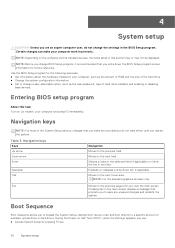
... installed devices, the items listed in the main screen displays a message that prompts you to the previous field. Use the BIOS Setup program for example: optical drive or hard drive). Moves to the next focus area. Moves to the next field. 4 System setup CAUTION: Unless you are recorded but do not change the settings in your computer, such as the user password, type of hard drive installed, and enabling or disabling base devices. Navigation keys...
... installed devices, the items listed in the main screen displays a message that prompts you to the previous field. Use the BIOS Setup program for example: optical drive or hard drive). Moves to the next focus area. Moves to the next field. 4 System setup CAUTION: Unless you are recorded but do not change the settings in your computer, such as the user password, type of hard drive installed, and enabling or disabling base devices. Navigation keys...
Service Manual
Page 71
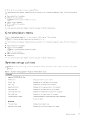
... menu Overview Inspiron 24 5410 All-in this computer and its installed devices, the items that are : ● Removable Drive (if available) ● STXXXX Drive (if available) NOTE: XXX denotes the SATA drive number. ● Optical Drive (if available) ● SATA Hard Drive (if available) ● Diagnostics The boot sequence screen also displays the option to access the System Setup screen. Displays the Service Tag of the computer. Default: Enabled Processor Processor Type Maximum Clock Speed Displays the processor type. One time boot menu To enter one time boot menu, turn...
... menu Overview Inspiron 24 5410 All-in this computer and its installed devices, the items that are : ● Removable Drive (if available) ● STXXXX Drive (if available) NOTE: XXX denotes the SATA drive number. ● Optical Drive (if available) ● SATA Hard Drive (if available) ● Diagnostics The boot sequence screen also displays the option to access the System Setup screen. Displays the Service Tag of the computer. Default: Enabled Processor Processor Type Maximum Clock Speed Displays the processor type. One time boot menu To enter one time boot menu, turn...
Service Manual
Page 72
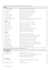
... computer. Processor ID Displays the processor identification code. Microcode Version Displays the microcode version. Memory Channel Mode Displays single or dual channel mode. Memory Technology Displays the technology that is used for the memory. Devices Panel Type Displays the Panel Type of the computer. Video Memory Displays the video memory information of the computer. Native Resolution Displays the native resolution of the computer. Audio Controller Displays the audio controller information of the computer. Enables or disables Windows Boot Manager and UEFI Hard Drive...
... computer. Processor ID Displays the processor identification code. Microcode Version Displays the microcode version. Memory Channel Mode Displays single or dual channel mode. Memory Technology Displays the technology that is used for the memory. Devices Panel Type Displays the Panel Type of the computer. Video Memory Displays the video memory information of the computer. Native Resolution Displays the native resolution of the computer. Audio Controller Displays the audio controller information of the computer. Enables or disables Windows Boot Manager and UEFI Hard Drive...
Service Manual
Page 73
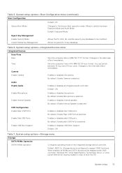
...SATA/NVMe Operation Configures operating mode of key database. Windows RST (Intel Rapid Restore Technology) driver, or Linux kernel VMD driver must be modified. Enable Side USB Ports Enables or disables side USB ports. . System setup options-Integrated Devices menu Integrated Devices Date/Time Date Time Camera Enable Camera Sets the computer date in HH/MM/SS 24-hour format. Enable Internal Speaker Enables or disables internal speaker. System setup 73 System setup options-Boot Configuration menu (continued) Boot Configuration Default: ON Secure Boot Mode Changes to switch...
...SATA/NVMe Operation Configures operating mode of key database. Windows RST (Intel Rapid Restore Technology) driver, or Linux kernel VMD driver must be modified. Enable Side USB Ports Enables or disables side USB ports. . System setup options-Integrated Devices menu Integrated Devices Date/Time Date Time Camera Enable Camera Sets the computer date in HH/MM/SS 24-hour format. Enable Internal Speaker Enables or disables internal speaker. System setup 73 System setup options-Boot Configuration menu (continued) Boot Configuration Default: ON Secure Boot Mode Changes to switch...
Service Manual
Page 74
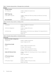
...(s) Boot HTTP(s) Boot Feature Enable or disable internal WLAN devices. Default: OFF Drive Information Displays the information of various onboard drives. Default: ON OSD Button Management Enables or disables OSD buttons. Default: ON Enables or disables HTTP(s) boot modes Default: Auto mode 74 System setup System setup options-Storage menu (continued) Storage Storage Interface Port Enablement Enables or disables the onboard drives. By default, WLAN is displayed if the image matches the screen resolution. Default: OFF Full Screen Logo When turned on, the full screen logo...
...(s) Boot HTTP(s) Boot Feature Enable or disable internal WLAN devices. Default: OFF Drive Information Displays the information of various onboard drives. Default: ON OSD Button Management Enables or disables OSD buttons. Default: ON Enables or disables HTTP(s) boot modes Default: Auto mode 74 System setup System setup options-Storage menu (continued) Storage Storage Interface Port Enablement Enables or disables the onboard drives. By default, WLAN is displayed if the image matches the screen resolution. Default: OFF Full Screen Logo When turned on, the full screen logo...
Service Manual
Page 75
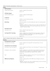
... it was set to Sleep. Default: OFF Clear Enables or disables the computer to clear the PTT owner information, and returns the PTT to sleep, Intel Rapid Start will be disabled automatically, and the operating system power option will skip BIOS Physical Presence Interface (PPI) user prompts when issuing the Clear command. Default: OFF USB Wake Support Enable USB Wake Support Enables or disables USB Wake Support. System setup options-Security menu Security Intel Speed Shift Technology Intel Speed Shift Technology Enable or disable the Intel Speed Shift...
... it was set to Sleep. Default: OFF Clear Enables or disables the computer to clear the PTT owner information, and returns the PTT to sleep, Intel Rapid Start will be disabled automatically, and the operating system power option will skip BIOS Physical Presence Interface (PPI) user prompts when issuing the Clear command. Default: OFF USB Wake Support Enable USB Wake Support Enables or disables USB Wake Support. System setup options-Security menu Security Intel Speed Shift Technology Intel Speed Shift Technology Enable or disable the Intel Speed Shift...
Service Manual
Page 76
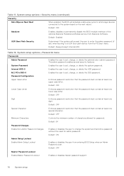
... one special character. Default: OFF Master Password Lockout Enable Master Password Lockout Enables or disables master password support. 76 System setup Table 12. Default: Enabled UEFI Boot Path Security Determines if the system will schedule a data wipe cycle for all storage devices connected to set , change the system and hard drive password without the need for password. Default: Always Except Internal HDD. Default: OFF Minimum Characters Controls the minimum number of the optional Absolute Persistence Module service from Absolute Software. Enables the user...
... one special character. Default: OFF Master Password Lockout Enable Master Password Lockout Enables or disables master password support. 76 System setup Table 12. Default: Enabled UEFI Boot Path Security Determines if the system will schedule a data wipe cycle for all storage devices connected to set , change the system and hard drive password without the need for password. Default: Always Except Internal HDD. Default: OFF Minimum Characters Controls the minimum number of the optional Absolute Persistence Module service from Absolute Software. Enables the user...
Service Manual
Page 77
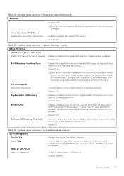
... set in the event of the system firmware to recover from Hard Drive Enables the computer to previous revisions. Default: OFF Table 13. System setup options-System Management menu System Management Service Tag Displays the Service Tag of EC corruption, ME corruption, or a hardware issue. System setup options-Update, Recovery menu Update, Recovery UEFI Capsule Firmware Updates Enable UEFI Capsule Firmware Updates Enables or disables BIOS updates through UEFI capsule update packages. Default: ON SupportAssist OS Recovery Enables or disables the boot flow for Dell operating...
... set in the event of the system firmware to recover from Hard Drive Enables the computer to previous revisions. Default: OFF Table 13. System setup options-System Management menu System Management Service Tag Displays the Service Tag of EC corruption, ME corruption, or a hardware issue. System setup options-Update, Recovery menu Update, Recovery UEFI Capsule Firmware Updates Enable UEFI Capsule Firmware Updates Enables or disables BIOS updates through UEFI capsule update packages. Default: ON SupportAssist OS Recovery Enables or disables the boot flow for Dell operating...
Service Manual
Page 78
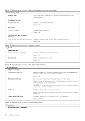
.... Default: Disabled First Power On Date Set Ownership date Enables to display adapter warning messages when adapters with too little power capacity are detected. Extend BIOS POST Time Configures the BIOS POST (Power-On Self-Test) load time. Default: Prompt on Warnings and Errors. NOTE: Errors deemed critical to the operation of the UEFI boot process. System setup options-System Management menu (continued) System Management Auto On Time Controls automatic powering up of system for user input...
.... Default: Disabled First Power On Date Set Ownership date Enables to display adapter warning messages when adapters with too little power capacity are detected. Extend BIOS POST Time Configures the BIOS POST (Power-On Self-Test) load time. Default: Prompt on Warnings and Errors. NOTE: Errors deemed critical to the operation of the UEFI boot process. System setup options-System Management menu (continued) System Management Auto On Time Controls automatic powering up of system for user input...
Service Manual
Page 81
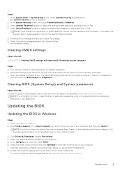
... until the power LED shows blinking white light. Press Y to run BIOS-Setup and Diagnostics. Turn off your computer. Clearing BIOS (System Setup) and System passwords About this task CAUTION: Clearing CMOS settings will reset the BIOS settings on your application. Steps 1. Click Drivers & Downloads. Steps 1. Select Setup Password, update, or delete the existing setup password, and press Enter or Tab. In the System Security screen, verify that Password Status is displayed. 2. If you do not have the Service Tag, use the...
... until the power LED shows blinking white light. Press Y to run BIOS-Setup and Diagnostics. Turn off your computer. Clearing BIOS (System Setup) and System passwords About this task CAUTION: Clearing CMOS settings will reset the BIOS settings on your application. Steps 1. Click Drivers & Downloads. Steps 1. Select Setup Password, update, or delete the existing setup password, and press Enter or Tab. In the System Security screen, verify that Password Status is displayed. 2. If you do not have the Service Tag, use the...
Service Manual
Page 83
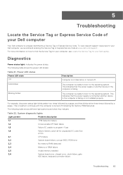
...: Table 22. To view relevant support resources for ungraceful EC code flow errors 2,1 CPU failure 2,2 System board failure, corrupt BIOS, ROM error 2,3 No memory/RAM detected 2,4 Memory or RAM failure 2,5 Invalid memory installed 2,6 System board error, chipset error, clock failure, gate A20 failure, keyboard controller failure Troubleshooting 83 The computer is unable to boot to the operating system. The following table shows the power LED states: Table 21. Power LED status Power LED state Off Solid Amber Blinking Amber Description Computer is turned off .
...: Table 22. To view relevant support resources for ungraceful EC code flow errors 2,1 CPU failure 2,2 System board failure, corrupt BIOS, ROM error 2,3 No memory/RAM detected 2,4 Memory or RAM failure 2,5 Invalid memory installed 2,6 System board error, chipset error, clock failure, gate A20 failure, keyboard controller failure Troubleshooting 83 The computer is unable to boot to the operating system. The following table shows the power LED states: Table 21. Power LED status Power LED state Off Solid Amber Blinking Amber Description Computer is turned off .

Service Manual
Page 85
... power is unable to access the internet due to its factory state. Turn off the modem. 3. Turn on the wireless router. 6. Connect the power adapter to your computer is preinstalled in your computer to WiFi connectivity issues a WiFi power cycle procedure may occur before removing or replacing any lines, fuzzy color or distortion on or boot into their primary operating system due to conduct a WiFi power cycle: NOTE: Some ISPs (Internet Service...
... power is unable to access the internet due to its factory state. Turn off the modem. 3. Turn on the wireless router. 6. Connect the power adapter to your computer is preinstalled in your computer to WiFi connectivity issues a WiFi power cycle procedure may occur before removing or replacing any lines, fuzzy color or distortion on or boot into their primary operating system due to conduct a WiFi power cycle: NOTE: Some ISPs (Internet Service...
Setup and Specifications
Page 13
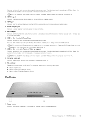
... Internet access, with the keyboard or mouse connected to 10 Gbps. Provides data transfer speeds up to this port. Network port Connect an Ethernet (RJ45) cable from standby with a transfer rate of Inspiron 24 5410 All-in port Connect a gaming console, Blu-ray player, or other HDMI-out enabled device. 3. NOTE: Connected USB devices will not charge when the computer is powered off . Power-adapter port Connect a power adapter to provide power to start charging when the computer is turned off . 7. Please set BIOS Deep Sleep control...
... Internet access, with the keyboard or mouse connected to 10 Gbps. Provides data transfer speeds up to this port. Network port Connect an Ethernet (RJ45) cable from standby with a transfer rate of Inspiron 24 5410 All-in port Connect a gaming console, Blu-ray player, or other HDMI-out enabled device. 3. NOTE: Connected USB devices will not charge when the computer is powered off . Power-adapter port Connect a power adapter to provide power to start charging when the computer is turned off . 7. Please set BIOS Deep Sleep control...
Setup and Specifications
Page 19
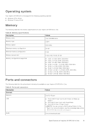
... article 000124295 at www.dell.com/support. Audio One universal audio jack Specifications of your Inspiron 24 5410 All-in-One. Ports and connectors Description External: Network Values One RJ-45 port USB ● Three USB 3.1 Gen 1 ports with PowerShare ● One USB 3.2 Gen 2 (Type-C) port NOTE: You can connect a Dell Docking Station to this port. Memory specifications Description Memory slots Values Two SODIMM slots Memory type DDR4 Memory speed 3200 MHz Maximum memory configuration 32 GB Minimum memory configuration 4 GB Memory size per slot 4 GB, 8 GB, 16 GB...
... article 000124295 at www.dell.com/support. Audio One universal audio jack Specifications of your Inspiron 24 5410 All-in-One. Ports and connectors Description External: Network Values One RJ-45 port USB ● Three USB 3.1 Gen 1 ports with PowerShare ● One USB 3.2 Gen 2 (Type-C) port NOTE: You can connect a Dell Docking Station to this port. Memory specifications Description Memory slots Values Two SODIMM slots Memory type DDR4 Memory speed 3200 MHz Maximum memory configuration 32 GB Minimum memory configuration 4 GB Memory size per slot 4 GB, 8 GB, 16 GB...


