Handling swollen Lithium-ion batteries
Page 1
... further instructions. ● Using a non-Dell or incompatible battery may increase the risk of lithium-ion battery is the potential for swelling of the battery cells Swollen battery may be replaced and disposed of the applicable warranty or service contract, including options for handling and replacing Lithium-ion batteries ● Exercise caution when handling Lithium-ion batteries. ● Discharge the battery before removing it from Dell...
... further instructions. ● Using a non-Dell or incompatible battery may increase the risk of lithium-ion battery is the potential for swelling of the battery cells Swollen battery may be replaced and disposed of the applicable warranty or service contract, including options for handling and replacing Lithium-ion batteries ● Exercise caution when handling Lithium-ion batteries. ● Discharge the battery before removing it from Dell...
Inspiron 15 5000 Service Manual
Page 3
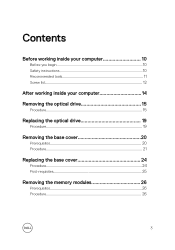
Contents Before working inside your computer 10 Before you begin 10 Safety instructions 10 Recommended tools 11 Screw list 12 After working inside your computer 14 Removing the optical drive 15 Procedure 15 Replacing the optical drive 19 Procedure 19 Removing the base cover 20 Prerequisites 20 Procedure 21 Replacing the base cover 24 Procedure 24 Post-requisites 25 Removing the memory modules 26 Prerequisites 26 Procedure 26 3
Contents Before working inside your computer 10 Before you begin 10 Safety instructions 10 Recommended tools 11 Screw list 12 After working inside your computer 14 Removing the optical drive 15 Procedure 15 Replacing the optical drive 19 Procedure 19 Removing the base cover 20 Prerequisites 20 Procedure 21 Replacing the base cover 24 Procedure 24 Post-requisites 25 Removing the memory modules 26 Prerequisites 26 Procedure 26 3
Inspiron 15 5000 Service Manual
Page 11
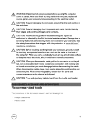
... the electrical outlet. See the safety instructions that shipped with locking tabs or thumb-screws that is not authorized by Dell is flat and clean. WARNING: Disconnect all covers, panels, and screws before connecting to avoid bending any installed card from the media-card reader. After you work surface is not covered by their edges, and avoid touching pins and contacts. CAUTION: To avoid...
... the electrical outlet. See the safety instructions that shipped with locking tabs or thumb-screws that is not authorized by Dell is flat and clean. WARNING: Disconnect all covers, panels, and screws before connecting to avoid bending any installed card from the media-card reader. After you work surface is not covered by their edges, and avoid touching pins and contacts. CAUTION: To avoid...
Inspiron 15 5000 Service Manual
Page 14
GUID-06588814-2678-4667-9FF9-C009F4BCE185 After working inside your computer CAUTION: Leaving stray or loose screws inside your computer may severely damage your computer. 1 Replace all screws and ensure that no stray screws remain inside your computer. 2 Connect any external devices, peripherals, or cables you removed before working on your computer. 3 Replace any media cards, discs, or any other parts that you removed before working on your computer. 4 Connect your computer and all attached devices to their electrical outlets. 5 Turn on your computer. 14
GUID-06588814-2678-4667-9FF9-C009F4BCE185 After working inside your computer CAUTION: Leaving stray or loose screws inside your computer may severely damage your computer. 1 Replace all screws and ensure that no stray screws remain inside your computer. 2 Connect any external devices, peripherals, or cables you removed before working on your computer. 3 Replace any media cards, discs, or any other parts that you removed before working on your computer. 4 Connect your computer and all attached devices to their electrical outlets. 5 Turn on your computer. 14

Inspiron 15 5000 Service Manual
Page 26
... the Regulatory Compliance home page at www.dell.com/ regulatory_compliance. GUID-B63E7AE3-1A63-42B8-8121-1A48547C357D Prerequisites 1 Remove the optical drive. 2 Remove the base cover. GUID-9031EF58-9B11-46DE-BC16-72882DFDDE0A Procedure 1 Use your fingertips to carefully spread apart the securing-clips on each end of the memory-module slot until the memory module pops up. 26 After working inside your computer, follow the steps...
... the Regulatory Compliance home page at www.dell.com/ regulatory_compliance. GUID-B63E7AE3-1A63-42B8-8121-1A48547C357D Prerequisites 1 Remove the optical drive. 2 Remove the base cover. GUID-9031EF58-9B11-46DE-BC16-72882DFDDE0A Procedure 1 Use your fingertips to carefully spread apart the securing-clips on each end of the memory-module slot until the memory module pops up. 26 After working inside your computer, follow the steps...
Inspiron 15 5000 Service Manual
Page 39
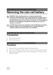
CAUTION: Removing the coin-cell battery resets the BIOS setup program's settings to default. It is recommended that shipped with your computer and follow the instructions in Before working inside your computer. GUID-B63E7AE3-1A63-42B8-8121-1A48547C357D Prerequisites 1 Remove the optical drive. 2 Remove the base cover. GUID-B5BD7027-9D38-47A1-AE58-B30BEB4BD9C6 Procedure 1 Disconnect the coin-cell battery cable from the system board. 2 Note the coin-cell battery cable routing...
CAUTION: Removing the coin-cell battery resets the BIOS setup program's settings to default. It is recommended that shipped with your computer and follow the instructions in Before working inside your computer. GUID-B63E7AE3-1A63-42B8-8121-1A48547C357D Prerequisites 1 Remove the optical drive. 2 Remove the base cover. GUID-B5BD7027-9D38-47A1-AE58-B30BEB4BD9C6 Procedure 1 Disconnect the coin-cell battery cable from the system board. 2 Note the coin-cell battery cable routing...

Inspiron 15 5000 Service Manual
Page 55
... and keyboard assembly. 2 Press down the status-light board until it snaps into place. 3 Adhere the status-light board cable to the palm rest and keyboard assembly. 4 Slide the status-light board cable into the connector on the system board and close the latch to secure the cable. GUID-1F9A097D-6ED1-4162-8C96-329D29AC0D98 Post-requisites 1 Replace the battery. 2 Replace the hard drive. 3 Replace the I/O board. 4 Replace the base cover. 5 Replace the optical drive...
... and keyboard assembly. 2 Press down the status-light board until it snaps into place. 3 Adhere the status-light board cable to the palm rest and keyboard assembly. 4 Slide the status-light board cable into the connector on the system board and close the latch to secure the cable. GUID-1F9A097D-6ED1-4162-8C96-329D29AC0D98 Post-requisites 1 Replace the battery. 2 Replace the hard drive. 3 Replace the I/O board. 4 Replace the base cover. 5 Replace the optical drive...

Inspiron 15 5000 Service Manual
Page 58
... follow the instructions in After working inside your computer. GUID-1F9A097D-6ED1-4162-8C96-329D29AC0D98 Post-requisites 1 Replace the battery. 2 Replace the hard drive. 3 Replace the I/O board. 4 Replace the base cover. 5 Replace the optical drive. 58 NOTE: Push the rubber gourmets inside if it pops out while replacing the speakers. 3 Connect the speaker cable to the system board. 4 Slide the status-light board cable into place. 2 Route the speaker cable through the...
... follow the instructions in After working inside your computer. GUID-1F9A097D-6ED1-4162-8C96-329D29AC0D98 Post-requisites 1 Replace the battery. 2 Replace the hard drive. 3 Replace the I/O board. 4 Replace the base cover. 5 Replace the optical drive. 58 NOTE: Push the rubber gourmets inside if it pops out while replacing the speakers. 3 Connect the speaker cable to the system board. 4 Slide the status-light board cable into place. 2 Route the speaker cable through the...

Inspiron 15 5000 Service Manual
Page 59
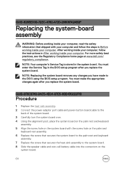
... shipped with your computer and follow the instructions in Before working inside your computer. GUID-C052C317-4BC4-481A-95A3-82980917C6F5 Prerequisites 1 Remove the optical drive. 2 Remove the base cover. 3 Remove the I/O board. 4 Remove the hard drive. 5 Remove the battery. 6 Remove the memory modules. 7 Remove the wireless card. 59 NOTE: Your computer's Service Tag is stored in the BIOS setup program after you have made to the BIOS using the BIOS setup program. For more safety best practices...
... shipped with your computer and follow the instructions in Before working inside your computer. GUID-C052C317-4BC4-481A-95A3-82980917C6F5 Prerequisites 1 Remove the optical drive. 2 Remove the base cover. 3 Remove the I/O board. 4 Remove the hard drive. 5 Remove the battery. 6 Remove the memory modules. 7 Remove the wireless card. 59 NOTE: Your computer's Service Tag is stored in the BIOS setup program after you have made to the BIOS using the BIOS setup program. For more safety best practices...
Inspiron 15 5000 Service Manual
Page 64
.... 2 Connect the power-adapter port cable and power-button board cable to the back of the system board. 3 Carefully turn the system board over. 4 Using the alignment post, place the system board on the palm rest and keyboard assembly. 5 Align the screw hole on the system board with your computer and follow the instructions in Before working inside your computer. NOTE: Your computer's Service Tag is stored in the BIOS setup...
.... 2 Connect the power-adapter port cable and power-button board cable to the back of the system board. 3 Carefully turn the system board over. 4 Using the alignment post, place the system board on the palm rest and keyboard assembly. 5 Align the screw hole on the system board with your computer and follow the instructions in Before working inside your computer. NOTE: Your computer's Service Tag is stored in the BIOS setup...

Inspiron 15 5000 Service Manual
Page 65
...-95E4-296FC791E7D1 Post-requisites 1 Replace the wireless card. 2 Replace the memory modules. 3 Replace the battery. 4 Replace the hard drive. 5 Replace the I/O board. 6 Replace the base cover. 7 Replace the optical drive. 65 9 Slide the touch-pad cable, keyboard backlight cable, and keyboard cable into the connectors and close the latches. 10 Slide the status-light board cable into the connector on the system board and close the latch. 11 Connect the optical-drive interposer cable to the system board and the opticaldrive interposer...
...-95E4-296FC791E7D1 Post-requisites 1 Replace the wireless card. 2 Replace the memory modules. 3 Replace the battery. 4 Replace the hard drive. 5 Replace the I/O board. 6 Replace the base cover. 7 Replace the optical drive. 65 9 Slide the touch-pad cable, keyboard backlight cable, and keyboard cable into the connectors and close the latches. 10 Slide the status-light board cable into the connector on the system board and close the latch. 11 Connect the optical-drive interposer cable to the system board and the opticaldrive interposer...
Inspiron 15 5000 Service Manual
Page 66
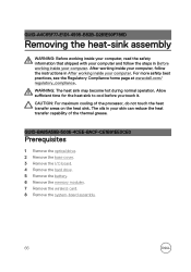
... become hot during normal operation. GUID-BA85A58B-5006-4CEE-BACF-CE1B91EE0CE0 Prerequisites 1 Remove the optical drive. 2 Remove the base cover. 3 Remove the I/O board. 4 Remove the hard drive. 5 Remove the battery. 6 Remove the memory modules. 7 Remove the wireless card. 8 Remove the system-board assembly. 66 GUID-A4C65F77-E1D1-4595-B52B-D281E90F786D Removing the heat-sink assembly WARNING: Before working inside your computer, read the safety information that shipped with your computer and follow the instructions in After working...
... become hot during normal operation. GUID-BA85A58B-5006-4CEE-BACF-CE1B91EE0CE0 Prerequisites 1 Remove the optical drive. 2 Remove the base cover. 3 Remove the I/O board. 4 Remove the hard drive. 5 Remove the battery. 6 Remove the memory modules. 7 Remove the wireless card. 8 Remove the system-board assembly. 66 GUID-A4C65F77-E1D1-4595-B52B-D281E90F786D Removing the heat-sink assembly WARNING: Before working inside your computer, read the safety information that shipped with your computer and follow the instructions in After working...
Inspiron 15 5000 Service Manual
Page 70
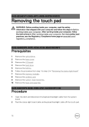
... 1 Remove the optical drive. 2 Remove the base cover. 3 Remove the I/O board. 4 Remove the hard drive. 5 Remove the battery. 6 Follow the procedure from the system board. 2 Peel the status-light board cable and keyboard backlight cable off the touch pad. 70 GUID-BA8026F6-8646-449B-A76C-9ADDD43FCC38 Procedure 1 Open the latch and disconnect the keyboard backlight cable from step 1 to step 2 in Before working inside your computer, follow the steps in "Removing the status-light board". 7 Remove the memory modules. 8 Remove the wireless card. 9 Remove...
... 1 Remove the optical drive. 2 Remove the base cover. 3 Remove the I/O board. 4 Remove the hard drive. 5 Remove the battery. 6 Follow the procedure from the system board. 2 Peel the status-light board cable and keyboard backlight cable off the touch pad. 70 GUID-BA8026F6-8646-449B-A76C-9ADDD43FCC38 Procedure 1 Open the latch and disconnect the keyboard backlight cable from step 1 to step 2 in Before working inside your computer, follow the steps in "Removing the status-light board". 7 Remove the memory modules. 8 Remove the wireless card. 9 Remove...

Inspiron 15 5000 Service Manual
Page 100
...-869F-F10535285070 Prerequisites 1 Remove the optical drive. 2 Remove the base cover. 3 Remove the I/O board. 4 Remove the hard drive. 5 Remove the battery. 6 Remove the memory modules. 7 Remove the wireless card. 8 Remove the system-board assembly. 9 Remove the heat-sink assembly. 10 Remove the display panel. GUID-E31FD4D2-D7F5-4CA7-80D8-5A6CE8099F41 Removing the power-button module WARNING: Before working inside your computer, read the safety information that secures the power-button board to the palm rest and keyboard assembly. 100 GUID-8D3D9F1C-96DF-4F0A-ABDB...
...-869F-F10535285070 Prerequisites 1 Remove the optical drive. 2 Remove the base cover. 3 Remove the I/O board. 4 Remove the hard drive. 5 Remove the battery. 6 Remove the memory modules. 7 Remove the wireless card. 8 Remove the system-board assembly. 9 Remove the heat-sink assembly. 10 Remove the display panel. GUID-E31FD4D2-D7F5-4CA7-80D8-5A6CE8099F41 Removing the power-button module WARNING: Before working inside your computer, read the safety information that secures the power-button board to the palm rest and keyboard assembly. 100 GUID-8D3D9F1C-96DF-4F0A-ABDB...
Inspiron 15 5000 Service Manual
Page 104
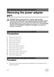
... 1 Remove the optical drive. 2 Remove the base cover. 3 Remove the I/O board. 4 Remove the hard drive. 5 Remove the battery. 6 Remove the status-light board. 7 Remove the memory modules. 8 Remove the wireless card. 9 Remove the system-board assembly. 10 Remove the heat-sink assembly. 11 Remove the display panel. GUID-6781AE98-7BE9-467E-92BB-7DC91BA697AC Procedure 1 Remove the screw that shipped with your computer and follow the instructions in Before working inside your computer. GUID-35D5032D-9652-403C-9A8A-F98FFABA8776 Removing the power-adapter port WARNING: Before working...
... 1 Remove the optical drive. 2 Remove the base cover. 3 Remove the I/O board. 4 Remove the hard drive. 5 Remove the battery. 6 Remove the status-light board. 7 Remove the memory modules. 8 Remove the wireless card. 9 Remove the system-board assembly. 10 Remove the heat-sink assembly. 11 Remove the display panel. GUID-6781AE98-7BE9-467E-92BB-7DC91BA697AC Procedure 1 Remove the screw that shipped with your computer and follow the instructions in Before working inside your computer. GUID-35D5032D-9652-403C-9A8A-F98FFABA8776 Removing the power-adapter port WARNING: Before working...

Inspiron 15 5000 Service Manual
Page 108
... optical drive. 2 Remove the base cover. 3 Remove the I/O board. 4 Remove the hard drive. 5 Remove the battery. 6 Remove the status-light board. 7 Remove the memory modules. 8 Remove the wireless card. 9 Remove the coin-cell battery. 10 Remove the system-board assembly. 11 Remove the heat-sink assembly. 12 Remove the touch pad. 13 Remove the speakers. 14 Remove the display back-cover and antenna assembly. 15 Remove the power-button module. 16 Remove the power-adapter port. 108 GUID-631184FE-18D9-4002-8F9F-DDB8690B3A74 Removing the palm rest and keyboard assembly WARNING: Before working inside...
... optical drive. 2 Remove the base cover. 3 Remove the I/O board. 4 Remove the hard drive. 5 Remove the battery. 6 Remove the status-light board. 7 Remove the memory modules. 8 Remove the wireless card. 9 Remove the coin-cell battery. 10 Remove the system-board assembly. 11 Remove the heat-sink assembly. 12 Remove the touch pad. 13 Remove the speakers. 14 Remove the display back-cover and antenna assembly. 15 Remove the power-button module. 16 Remove the power-adapter port. 108 GUID-631184FE-18D9-4002-8F9F-DDB8690B3A74 Removing the palm rest and keyboard assembly WARNING: Before working inside...

Inspiron 15 5000 Service Manual
Page 112
... toggle this light between power and battery-status light and hard-drive activity light. The following table shows the different power and battery-status light patterns and the problems that each light pattern indicate. The power and battery-status light blinks amber along with beep codes indicating failures. This 2,3 pattern continues until the computer is turned off indicating no memory or RAM is in sleep state, hibernation, or turned off. For example, the power and battery-status light blinks amber...
... toggle this light between power and battery-status light and hard-drive activity light. The following table shows the different power and battery-status light patterns and the problems that each light pattern indicate. The power and battery-status light blinks amber along with beep codes indicating failures. This 2,3 pattern continues until the computer is turned off indicating no memory or RAM is in sleep state, hibernation, or turned off. For example, the power and battery-status light blinks amber...

Inspiron 15 5000 Service Manual
Page 113
Camera is not in use. • Off - Camera is in use . • Solid white - Caps Lock enabled. • Off - Caps Lock disabled. 113 Light pattern 2,3 2,4 2,5 2,6 2,7 3,1 3,2 3,3 3,4 Problem description No memory or RAM detected Memory or RAM failure Invalid memory installed System board or chipset error LCD failure CMOS battery failure PCI or video card or chip failure Recovery image not found Recovery image found but invalid Camera status light: Indicates whether the camera is enabled or disabled. • Solid white - Caps Lock status light: Indicates whether...
Camera is not in use. • Off - Camera is in use . • Solid white - Caps Lock enabled. • Off - Caps Lock disabled. 113 Light pattern 2,3 2,4 2,5 2,6 2,7 3,1 3,2 3,3 3,4 Problem description No memory or RAM detected Memory or RAM failure Invalid memory installed System board or chipset error LCD failure CMOS battery failure PCI or video card or chip failure Recovery image not found Recovery image found but invalid Camera status light: Indicates whether the camera is enabled or disabled. • Solid white - Caps Lock status light: Indicates whether...
Inspiron 15 5000 Setup and Specifications
Page 8
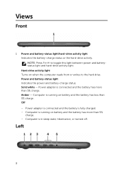
... 5% charge. Computer is fully charged. - NOTE: Press Fn+H to the hard drive. Off - Hard-drive activity light Turns on battery and the battery has less than 5% charge. - Amber - Power adapter is connected and the battery is running on when the computer reads from or writes to toggle this light between power and batterystatus light and hard-drive activity light. Views Front 1 Power and battery-status light/hard-drive activity light Indicates the battery-charge status or the hard-drive activity. Computer is in sleep state, hibernation, or turned...
... 5% charge. Computer is fully charged. - NOTE: Press Fn+H to the hard drive. Off - Hard-drive activity light Turns on battery and the battery has less than 5% charge. - Amber - Power adapter is connected and the battery is running on when the computer reads from or writes to toggle this light between power and batterystatus light and hard-drive activity light. Views Front 1 Power and battery-status light/hard-drive activity light Indicates the battery-charge status or the hard-drive activity. Computer is in sleep state, hibernation, or turned...
Inspiron 15 5000 Setup and Specifications
Page 19
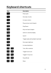
Keyboard shortcuts Keys Description Mute audio Decrease volume Increase volume Play previous track/chapter Play/Pause Play next track/chapter Switch to external display Search Toggle keyboard backlight (optional) Decrease brightness Increase brightness Turn off/on wireless Toggle Scroll Lock Toggle Fn-key lock Pause/Break Sleep 19
Keyboard shortcuts Keys Description Mute audio Decrease volume Increase volume Play previous track/chapter Play/Pause Play next track/chapter Switch to external display Search Toggle keyboard backlight (optional) Decrease brightness Increase brightness Turn off/on wireless Toggle Scroll Lock Toggle Fn-key lock Pause/Break Sleep 19


