Specifications
Page 3
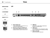
... video and audio output. 4 USB 3.0 port Connect peripherals such as storage devices, printers, and so on. Provides data transfer speeds up to 5 Gbps. 5 Media-card reader Reads from and writes to your computer and charge the battery. 2 Network port (Inspiron 15-5558 only) Connect an Ethernet (RJ45) cable from a router or a broadband modem for network or internet access. 3 HDMI port Connect a TV or another HDMI‑in enabled device. Specifications Front Left Left 12 Views 3 4 5 Right Base Display 1 Power-adapter port Connect a power adapter...
... video and audio output. 4 USB 3.0 port Connect peripherals such as storage devices, printers, and so on. Provides data transfer speeds up to 5 Gbps. 5 Media-card reader Reads from and writes to your computer and charge the battery. 2 Network port (Inspiron 15-5558 only) Connect an Ethernet (RJ45) cable from a router or a broadband modem for network or internet access. 3 HDMI port Connect a TV or another HDMI‑in enabled device. Specifications Front Left Left 12 Views 3 4 5 Right Base Display 1 Power-adapter port Connect a power adapter...

Specifications
Page 9
Views Memory Slots Type Speed Configurations supported Specifications Inspiron 15-5558 Two SODIMM slots Dual-channel DDR3L 1600 MHz 2 GB, 4 GB, 6 GB, 8 GB, 12 GB, and 16 GB Inspiron 15-5551 One SODIMM slot Single-channel DDR3L 1600 MHz 2 GB, 4 GB, and 8 GB Dimensions and weight System information Memory Ports and connectors Communications Video Audio Storage Media-card reader Display Keyboard Camera Touch pad Battery Power adapter Computer environment
Views Memory Slots Type Speed Configurations supported Specifications Inspiron 15-5558 Two SODIMM slots Dual-channel DDR3L 1600 MHz 2 GB, 4 GB, 6 GB, 8 GB, 12 GB, and 16 GB Inspiron 15-5551 One SODIMM slot Single-channel DDR3L 1600 MHz 2 GB, 4 GB, and 8 GB Dimensions and weight System information Memory Ports and connectors Communications Video Audio Storage Media-card reader Display Keyboard Camera Touch pad Battery Power adapter Computer environment
Specifications
Page 10
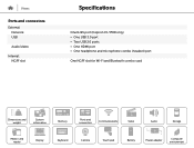
Views Ports and connectors External: Network USB Audio/video Internal: NGFF slot Specifications One RJ45 port (Inspiron 15-5558 only) • One USB 3.0 port • Two USB 2.0 ports • One HDMI port • One headphone and microphone combo (headset) port One NGFF slot for Wi-Fi and Bluetooth combo card Dimensions and weight System information Memory Ports and connectors Communications Video Audio Storage Media-card reader Display Keyboard Camera Touch pad Battery Power adapter Computer environment
Views Ports and connectors External: Network USB Audio/video Internal: NGFF slot Specifications One RJ45 port (Inspiron 15-5558 only) • One USB 3.0 port • Two USB 2.0 ports • One HDMI port • One headphone and microphone combo (headset) port One NGFF slot for Wi-Fi and Bluetooth combo card Dimensions and weight System information Memory Ports and connectors Communications Video Audio Storage Media-card reader Display Keyboard Camera Touch pad Battery Power adapter Computer environment
Specifications
Page 12
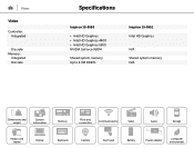
Views Video Controller: Integrated Discrete Memory: Integrated Discrete Specifications Inspiron 15-5558 • Intel HD Graphics • Intel HD Graphics 4400 • Intel HD Graphics 5500 NVIDIA GeForce 920M Shared system memory Up to 4 GB DDR3L Inspiron 15-5551 Intel HD Graphics N/A Shared system memory N/A Dimensions and weight System information Memory Ports and connectors Communications Video Audio Storage Media-card reader Display Keyboard Camera Touch pad Battery Power adapter Computer environment
Views Video Controller: Integrated Discrete Memory: Integrated Discrete Specifications Inspiron 15-5558 • Intel HD Graphics • Intel HD Graphics 4400 • Intel HD Graphics 5500 NVIDIA GeForce 920M Shared system memory Up to 4 GB DDR3L Inspiron 15-5551 Intel HD Graphics N/A Shared system memory N/A Dimensions and weight System information Memory Ports and connectors Communications Video Audio Storage Media-card reader Display Keyboard Camera Touch pad Battery Power adapter Computer environment
Specifications
Page 13
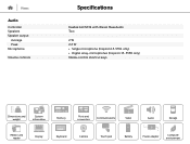
Views Audio Controller Speakers Speaker output: Average Peak Microphone Volume controls Specifications Realtek ALC3234 with Waves MaxxAudio Two 2 W 2.2 W • Single microphone (Inspiron 15-5551 only) • Digital array-microphones (Inspiron 15-5558 only) Media-control shortcut keys Dimensions and weight System information Memory Ports and connectors Communications Video Audio Storage Media-card reader Display Keyboard Camera Touch pad Battery Power adapter Computer environment
Views Audio Controller Speakers Speaker output: Average Peak Microphone Volume controls Specifications Realtek ALC3234 with Waves MaxxAudio Two 2 W 2.2 W • Single microphone (Inspiron 15-5551 only) • Digital array-microphones (Inspiron 15-5558 only) Media-control shortcut keys Dimensions and weight System information Memory Ports and connectors Communications Video Audio Storage Media-card reader Display Keyboard Camera Touch pad Battery Power adapter Computer environment
Specifications
Page 14
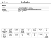
Views Storage Interface Hard drive Optical drive Drive supported Specifications • SATA 3 Gbps (Inspiron 15-5551 only) • SATA 6 Gbps (Inspiron 15-5558 only) One 2.5-inch drive (supports Intel Smart Response Technology) One 9.5 mm SATA drive DVD +/- RW Dimensions and weight System information Memory Ports and connectors Communications Video Audio Storage Media-card reader Display Keyboard Camera Touch pad Battery Power adapter Computer environment
Views Storage Interface Hard drive Optical drive Drive supported Specifications • SATA 3 Gbps (Inspiron 15-5551 only) • SATA 6 Gbps (Inspiron 15-5558 only) One 2.5-inch drive (supports Intel Smart Response Technology) One 9.5 mm SATA drive DVD +/- RW Dimensions and weight System information Memory Ports and connectors Communications Video Audio Storage Media-card reader Display Keyboard Camera Touch pad Battery Power adapter Computer environment
Specifications
Page 16
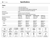
... weight System information Memory Ports and connectors Communications Video Audio Storage Media-card reader Display Keyboard Camera Touch pad Battery Power adapter Computer environment Views Display Type Refresh rate Operating angle Controls Resolution (maximum) Pixel pitch Dimensions: Height Width Diagonal Specifications • 15.6-inch HD Touch • 15.6-inch HD Non-touch • 15.6-inch FHD Non-touch (Inspiron 15-5558 only) • 15.6-inch FHD Touch (Inspiron 15-5558 only) 60 Hz 0 degrees (closed) to 135 degrees Brightness can be controlled using shortcut keys.
... weight System information Memory Ports and connectors Communications Video Audio Storage Media-card reader Display Keyboard Camera Touch pad Battery Power adapter Computer environment Views Display Type Refresh rate Operating angle Controls Resolution (maximum) Pixel pitch Dimensions: Height Width Diagonal Specifications • 15.6-inch HD Touch • 15.6-inch HD Non-touch • 15.6-inch FHD Non-touch (Inspiron 15-5558 only) • 15.6-inch FHD Touch (Inspiron 15-5558 only) 60 Hz 0 degrees (closed) to 135 degrees Brightness can be controlled using shortcut keys.
Specifications
Page 17
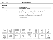
... be used to type alternate characters or to perform secondary functions. List of the shortcut keys by pressing Fn+Esc or by changing Function Key Behavior in BIOS setup program. Dimensions and weight System information Memory Ports and connectors Communications Video Audio Storage Media-card reader Display Keyboard Camera Touch pad Battery Power adapter Computer environment To type the alternate character, press Shift and the desired key. To perform secondary functions, press Fn and the desired key. Views Keyboard Type Shortcut keys Specifications...
... be used to type alternate characters or to perform secondary functions. List of the shortcut keys by pressing Fn+Esc or by changing Function Key Behavior in BIOS setup program. Dimensions and weight System information Memory Ports and connectors Communications Video Audio Storage Media-card reader Display Keyboard Camera Touch pad Battery Power adapter Computer environment To type the alternate character, press Shift and the desired key. To perform secondary functions, press Fn and the desired key. Views Keyboard Type Shortcut keys Specifications...
Specifications
Page 18
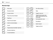
Keyboard Shortcut keys Mute audio Decrease volume Increase volume Play previous track/chapter Play/Pause Play next track/chapter Switch to external display Search Toggle keyboard backlight (optional) Decrease brightness Increase brightness Turn off/on wireless Sleep Toggle Fn-key lock Toggle between power and battery-status light/hard-drive activity light Open application menu Pause/Break System request Toggle scroll lock
Keyboard Shortcut keys Mute audio Decrease volume Increase volume Play previous track/chapter Play/Pause Play next track/chapter Switch to external display Search Toggle keyboard backlight (optional) Decrease brightness Increase brightness Turn off/on wireless Sleep Toggle Fn-key lock Toggle between power and battery-status light/hard-drive activity light Open application menu Pause/Break System request Toggle scroll lock
Service Manual
Page 4
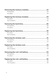
Removing the memory modules 22 Prerequisites...22 Procedure...22 Replacing the memory modules 24 Procedure...24 Post-requisites 25 Removing the hard drive 26 Prerequisites...26 Procedure...26 Replacing the hard drive 30 Procedure...30 Post-requisites 30 Removing the wireless card 31 Prerequisites...31 Procedure...31 Replacing the wireless card 33 Procedure...33 Post-requisites 33 Removing the coin-cell battery 34 Prerequisites...34 Procedure...34 Replacing the coin-cell battery 36 Procedure...36 Post-requisites 36 4
Removing the memory modules 22 Prerequisites...22 Procedure...22 Replacing the memory modules 24 Procedure...24 Post-requisites 25 Removing the hard drive 26 Prerequisites...26 Procedure...26 Replacing the hard drive 30 Procedure...30 Post-requisites 30 Removing the wireless card 31 Prerequisites...31 Procedure...31 Replacing the wireless card 33 Procedure...33 Post-requisites 33 Removing the coin-cell battery 34 Prerequisites...34 Procedure...34 Replacing the coin-cell battery 36 Procedure...36 Post-requisites 36 4
Service Manual
Page 10
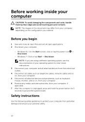
... the configuration you ordered. Before you begin 1 Save and close all open files and exit all open applications. 2 Shut down instructions. 3 Disconnect your computer and all attached devices and peripherals, such as keyboard, mouse, monitor, and so on, from your computer. 6 Remove any media card and optical disc from your computer, if applicable. 7 After the computer is unplugged, press and hold the power button for...
... the configuration you ordered. Before you begin 1 Save and close all open files and exit all open applications. 2 Shut down instructions. 3 Disconnect your computer and all attached devices and peripherals, such as keyboard, mouse, monitor, and so on, from your computer. 6 Remove any media card and optical disc from your computer, if applicable. 7 After the computer is unplugged, press and hold the power button for...

Service Manual
Page 11
... assistance team. Damage due to avoid bending any installed card from the network device. CAUTION: When you must disengage before opening the computer cover or panels. WARNING: Before working inside the computer, replace all power sources before disconnecting the cable. Some cables have connectors with your computer, read the safety information that shipped with locking tabs or thumb-screws that shipped with the...
... assistance team. Damage due to avoid bending any installed card from the network device. CAUTION: When you must disengage before opening the computer cover or panels. WARNING: Before working inside the computer, replace all power sources before disconnecting the cable. Some cables have connectors with your computer, read the safety information that shipped with locking tabs or thumb-screws that shipped with the...
Service Manual
Page 13
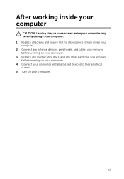
After working inside your computer CAUTION: Leaving stray or loose screws inside your computer may severely damage your computer. 1 Replace all screws and ensure that no stray screws remain inside your computer. 2 Connect any external devices, peripherals, and cables you removed before working on your computer. 3 Replace any media cards, discs, and any other parts that you removed before working on your computer. 4 Connect your computer and all attached devices to their electrical outlets. 5 Turn on your computer. 13
After working inside your computer CAUTION: Leaving stray or loose screws inside your computer may severely damage your computer. 1 Replace all screws and ensure that no stray screws remain inside your computer. 2 Connect any external devices, peripherals, and cables you removed before working on your computer. 3 Replace any media cards, discs, and any other parts that you removed before working on your computer. 4 Connect your computer and all attached devices to their electrical outlets. 5 Turn on your computer. 13
Service Manual
Page 22
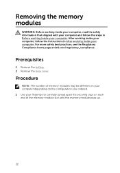
... computer depending on the configuration you ordered. 1 Use your fingertips to carefully spread apart the securing clips on each end of the memory-module slot until the memory module pops up. 22 Removing the memory modules WARNING: Before working inside your computer, read the safety information that shipped with your computer and follow the instructions in Before working inside your computer. Prerequisites 1 Remove the battery. 2 Remove the base cover.
... computer depending on the configuration you ordered. 1 Use your fingertips to carefully spread apart the securing clips on each end of the memory-module slot until the memory module pops up. 22 Removing the memory modules WARNING: Before working inside your computer, read the safety information that shipped with your computer and follow the instructions in Before working inside your computer. Prerequisites 1 Remove the battery. 2 Remove the base cover.
Service Manual
Page 25
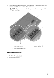
2 Slide the memory module firmly into the slot at an angle and press the memory module down until it . 1 memory module 3 memory-module slot Post-requisites 1 Replace the base cover. 2 Replace the battery. 2 securing clips (2) 25 NOTE: If you do not hear the click, remove the memory module and reinstall it clicks into place.
2 Slide the memory module firmly into the slot at an angle and press the memory module down until it . 1 memory module 3 memory-module slot Post-requisites 1 Replace the base cover. 2 Replace the battery. 2 securing clips (2) 25 NOTE: If you do not hear the click, remove the memory module and reinstall it clicks into place.
Service Manual
Page 34
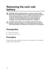
... battery. 2 Remove the base cover. Procedure Using a plastic scribe, gently pry out the coin-cell battery out of the battery socket on the system board. 34 For more safety best practices, see the Regulatory Compliance home page at dell.com/regulatory_compliance. Removing the coin-cell battery WARNING: Before working inside your computer, read the safety information that you note the BIOS setup program's settings...
... battery. 2 Remove the base cover. Procedure Using a plastic scribe, gently pry out the coin-cell battery out of the battery socket on the system board. 34 For more safety best practices, see the Regulatory Compliance home page at dell.com/regulatory_compliance. Removing the coin-cell battery WARNING: Before working inside your computer, read the safety information that you note the BIOS setup program's settings...
Service Manual
Page 63
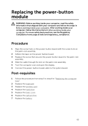
... 3 to the system board. After working inside your computer, follow the steps in "Replacing the computer base". 2 Replace the keyboard. 3 Replace the wireless card. 4 Replace the hard drive. 5 Replace the base cover. 6 Replace the optical drive. 7 Replace the battery. 63 Replacing the power-button module WARNING: Before working inside your computer, read the safety information that secures the power-button board to the palm-rest assembly. 4 Slide the cable through the slot on the power-button board. 3 Replace the screw that...
... 3 to the system board. After working inside your computer, follow the steps in "Replacing the computer base". 2 Replace the keyboard. 3 Replace the wireless card. 4 Replace the hard drive. 5 Replace the base cover. 6 Replace the optical drive. 7 Replace the battery. 63 Replacing the power-button module WARNING: Before working inside your computer, read the safety information that secures the power-button board to the palm-rest assembly. 4 Slide the cable through the slot on the power-button board. 3 Replace the screw that...
Service Manual
Page 64
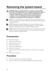
... follow the instructions in After working inside your computer. NOTE: Before disconnecting the cables from the system board. 64 For more safety best practices, see the Regulatory Compliance home page at dell.com/regulatory_compliance. Prerequisites 1 Remove the battery. 2 Remove the optical drive. 3 Remove the base cover. 4 Remove the hard drive. 5 Remove the wireless card. 6 Remove the keyboard. 7 Follow the procedure from step 1 to the BIOS using the BIOS setup program. After working inside your...
... follow the instructions in After working inside your computer. NOTE: Before disconnecting the cables from the system board. 64 For more safety best practices, see the Regulatory Compliance home page at dell.com/regulatory_compliance. Prerequisites 1 Remove the battery. 2 Remove the optical drive. 3 Remove the base cover. 4 Remove the hard drive. 5 Remove the wireless card. 6 Remove the keyboard. 7 Follow the procedure from step 1 to the BIOS using the BIOS setup program. After working inside your...
Service Manual
Page 69
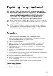
... the system board. Procedure 1 Connect the power-adapter port cable to the system board. 2 Slide the I /O board. 69 You must make the desired changes again after you replace the system board. You must enter the Service Tag in After working inside your computer. Post-requisites 1 Replace the I /O-board cable into the connector and press down on the system board with your computer and follow the instructions in the BIOS setup program after...
... the system board. Procedure 1 Connect the power-adapter port cable to the system board. 2 Slide the I /O board. 69 You must make the desired changes again after you replace the system board. You must enter the Service Tag in After working inside your computer. Post-requisites 1 Replace the I /O-board cable into the connector and press down on the system board with your computer and follow the instructions in the BIOS setup program after...
Service Manual
Page 100
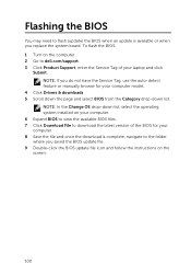
... when you do not have the Service Tag, use the auto-detect feature or manually browse for your laptop and click Submit. To flash the BIOS: 1 Turn on the computer. 2 Go to dell.com/support. 3 Click Product Support, enter the Service Tag of your computer model. 4 Click Drivers & downloads. 5 Scroll down the page and select BIOS from the Category drop-down list, select the operating system installed on the screen. 100
... when you do not have the Service Tag, use the auto-detect feature or manually browse for your laptop and click Submit. To flash the BIOS: 1 Turn on the computer. 2 Go to dell.com/support. 3 Click Product Support, enter the Service Tag of your computer model. 4 Click Drivers & downloads. 5 Scroll down the page and select BIOS from the Category drop-down list, select the operating system installed on the screen. 100


