Owners Manual
Page 19
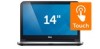
4 Lift and slide the keyboard towards the display to release the keyboard from the palm-rest and place the keyboard on the palm-rest. 5 Lift the connector latch and disconnect the keyboard cable from the keyboard-cable connector. 6 Lift the keyboard off the palm-rest. 1 2 1 keyboard 3 keyboard cable 4 3 2 palm-rest 4 connector latch Removing the Keyboard | 19
4 Lift and slide the keyboard towards the display to release the keyboard from the palm-rest and place the keyboard on the palm-rest. 5 Lift the connector latch and disconnect the keyboard cable from the keyboard-cable connector. 6 Lift the keyboard off the palm-rest. 1 2 1 keyboard 3 keyboard cable 4 3 2 palm-rest 4 connector latch Removing the Keyboard | 19
Owners Manual
Page 33
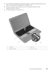
3 Turn the computer over and open the display as far as possible. 4 Remove the screws that secure the palm-rest to the computer base. 5 Lift the connector latches and, using the pull-tabs, disconnect the touchpad cable and the power-button cable from the system board. 1 2 1 power-button cable 3 connector latches (2) 5 touchpad cable 34 5 2 screws (4) 4 pull-tab Removing the Palm-Rest | 33
3 Turn the computer over and open the display as far as possible. 4 Remove the screws that secure the palm-rest to the computer base. 5 Lift the connector latches and, using the pull-tabs, disconnect the touchpad cable and the power-button cable from the system board. 1 2 1 power-button cable 3 connector latches (2) 5 touchpad cable 34 5 2 screws (4) 4 pull-tab Removing the Palm-Rest | 33
Owners Manual
Page 35
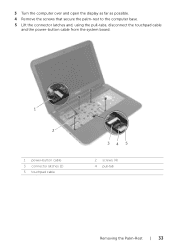
... secure the palm-rest to the computer base. 4 Slide the touchpad cable and the power-button cable into the system-board connectors and press down on the connector latches to secure the cables. 5 Close the display and turn the computer over. 6 Replace the screws that shipped with ...Palm-Rest | 35 See "Replacing the Base Cover" on page 13. For additional safety best practices information, see the Regulatory Compliance Homepage at dell.com/regulatory_compliance. See "Replacing the Battery" on page 22. 4 Replace the battery. Replacing the Palm-Rest WARNING: Before working inside your ...
... secure the palm-rest to the computer base. 4 Slide the touchpad cable and the power-button cable into the system-board connectors and press down on the connector latches to secure the cables. 5 Close the display and turn the computer over. 6 Replace the screws that shipped with ...Palm-Rest | 35 See "Replacing the Base Cover" on page 13. For additional safety best practices information, see the Regulatory Compliance Homepage at dell.com/regulatory_compliance. See "Replacing the Battery" on page 22. 4 Replace the battery. Replacing the Palm-Rest WARNING: Before working inside your ...
Owners Manual
Page 43
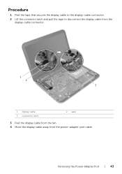
Removing the Power-Adapter Port | 43 Procedure 1 Peel the tape that secures the display cable to the display-cable connector. 2 Lift the connector latch and pull the tape to disconnect the display cable from the display-cable connector. 1 2 3 1 display cable 3 connector latch 2 tape 3 Peel the display cable from the fan. 4 Move the display cable away from the power-adapter-port cable.
Removing the Power-Adapter Port | 43 Procedure 1 Peel the tape that secures the display cable to the display-cable connector. 2 Lift the connector latch and pull the tape to disconnect the display cable from the display-cable connector. 1 2 3 1 display cable 3 connector latch 2 tape 3 Peel the display cable from the fan. 4 Move the display cable away from the power-adapter-port cable.
Owners Manual
Page 45
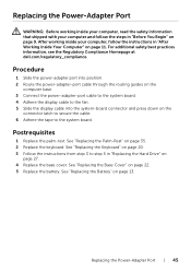
...adapter port into position. 2 Route the power-adapter-port cable through the routing guides on the computer base. 3 Connect the power-adapter-port cable to the system board. 4 Adhere the display cable to the fan. 5 Slide the display cable into the system-board connector and press down on page ...35. 2 Replace the keyboard. Replacing the Power-Adapter Port | 45 For additional safety best practices information, see the Regulatory Compliance Homepage at dell.com/regulatory_compliance. See "Replacing the Battery" on page 27. 4 Replace the base cover. See "Replacing the Keyboard" on page 20....
...adapter port into position. 2 Route the power-adapter-port cable through the routing guides on the computer base. 3 Connect the power-adapter-port cable to the system board. 4 Adhere the display cable to the fan. 5 Slide the display cable into the system-board connector and press down on page ...35. 2 Replace the keyboard. Replacing the Power-Adapter Port | 45 For additional safety best practices information, see the Regulatory Compliance Homepage at dell.com/regulatory_compliance. See "Replacing the Battery" on page 27. 4 Replace the base cover. See "Replacing the Keyboard" on page 20....
Owners Manual
Page 47
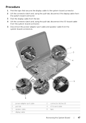
... the display cable from the system-board connector. 3 Peel the display cable from the fan. 4 Lift the connector latch and, using the pull-tab, disconnect the I/O-board cable from the system-board connector. 5 Disconnect the power-adapter-port cable and speaker cable from the system-board connectors. 2 3 4 1 7 6 1 power-adapter-port cable 3 pull-tab 5 speaker cable 7 display cable 5 2 connector latches (2) 4 I/O-board cable 6 tape...
... the display cable from the system-board connector. 3 Peel the display cable from the fan. 4 Lift the connector latch and, using the pull-tab, disconnect the I/O-board cable from the system-board connector. 5 Disconnect the power-adapter-port cable and speaker cable from the system-board connectors. 2 3 4 1 7 6 1 power-adapter-port cable 3 pull-tab 5 speaker cable 7 display cable 5 2 connector latches (2) 4 I/O-board cable 6 tape...

Owners Manual
Page 49
...the system-board ports into the system-board connector and press down on the connector latch to secure the cable. 7 Adhere the display cable to the fan. 8 Slide the display cable into the slots on the computer base and align the screw hole on the system board with the screw ... the system-board connectors. 6 Slide the I/O-board cable into the system-board connector and press down on page 35. 3 Replace the keyboard. For additional safety best practices information, see the Regulatory Compliance Homepage at dell.com/regulatory_compliance. See "Replacing the Memory Module(s)" on page 38 2 ...
...the system-board ports into the system-board connector and press down on the connector latch to secure the cable. 7 Adhere the display cable to the fan. 8 Slide the display cable into the slots on the computer base and align the screw hole on the system board with the screw ... the system-board connectors. 6 Slide the I/O-board cable into the system-board connector and press down on page 35. 3 Replace the keyboard. For additional safety best practices information, see the Regulatory Compliance Homepage at dell.com/regulatory_compliance. See "Replacing the Memory Module(s)" on page 38 2 ...
Owners Manual
Page 57
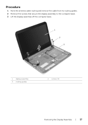
Procedure 1 Note the antenna cable routing and remove the cable from its routing guides. 2 Remove the screws that secure the display assembly to the computer base. 3 Lift the display assembly off the computer base. 1 2 3 1 display assembly 3 routing guides 2 screws (4) Removing the Display Assembly | 57
Procedure 1 Note the antenna cable routing and remove the cable from its routing guides. 2 Remove the screws that secure the display assembly to the computer base. 3 Lift the display assembly off the computer base. 1 2 3 1 display assembly 3 routing guides 2 screws (4) Removing the Display Assembly | 57

Owners Manual
Page 58
...computer, read the safety information that shipped with the screw holes on the computer base. 2 Replace the screws that secure the display assembly to step 4 in "After Working Inside Your Computer" on the computer base. For additional safety best practices information, see... the Regulatory Compliance Homepage at dell.com/regulatory_compliance. Postrequisites 1 Follow the instructions from step 3 to the computer base. 3 Route the antenna cable through the routing guides on page 11. After working inside your computer and ...
...computer, read the safety information that shipped with the screw holes on the computer base. 2 Replace the screws that secure the display assembly to step 4 in "After Working Inside Your Computer" on the computer base. For additional safety best practices information, see... the Regulatory Compliance Homepage at dell.com/regulatory_compliance. Postrequisites 1 Follow the instructions from step 3 to the computer base. 3 Route the antenna cable through the routing guides on page 11. After working inside your computer and ...
Owners Manual
Page 66
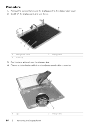
Procedure 1 Remove the screws that secure the display panel to the display back-cover. 2 Gently lift the display panel and turn it over. 1 2 3 1 display back-cover 3 screw (4) 2 display panel 3 Peel the tape adhered over the display cable. 4 Disconnect the display cable from the display-panel cable connector. 1 tape 66 | Removing the Display Panel 12 2 display cable
Procedure 1 Remove the screws that secure the display panel to the display back-cover. 2 Gently lift the display panel and turn it over. 1 2 3 1 display back-cover 3 screw (4) 2 display panel 3 Peel the tape adhered over the display cable. 4 Disconnect the display cable from the display-panel cable connector. 1 tape 66 | Removing the Display Panel 12 2 display cable
Owners Manual
Page 67
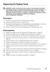
... Drive" on page 49. 5 Replace the palm-rest. Replacing the Display Panel | 67 For additional safety best practices information, see the Regulatory Compliance Homepage at dell.com/regulatory_compliance. See "Replacing the Display Hinges" on page 20. 7 Replace the wireless Mini-Card. See ...See "Replacing the Battery" on page 35. 6 Replace the keyboard. Postrequisites 1 Replace the display hinges. Procedure 1 Connect the display cable to the display-panel connector. 2 Adhere the tape that secure the display panel to step 5 in "Replacing the Hard Drive" on page 30. 8 Follow the ...
... Drive" on page 49. 5 Replace the palm-rest. Replacing the Display Panel | 67 For additional safety best practices information, see the Regulatory Compliance Homepage at dell.com/regulatory_compliance. See "Replacing the Display Hinges" on page 20. 7 Replace the wireless Mini-Card. See ...See "Replacing the Battery" on page 35. 6 Replace the keyboard. Postrequisites 1 Replace the display hinges. Procedure 1 Connect the display cable to the display-panel connector. 2 Adhere the tape that secure the display panel to step 5 in "Replacing the Hard Drive" on page 30. 8 Follow the ...
Owners Manual
Page 69
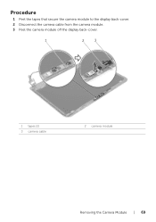
Procedure 1 Peel the tapes that secure the camera module to the display back-cover. 2 Disconnect the camera cable from the camera module. 3 Peel the camera module off the display back-cover. 1 2 3 1 tapes (2) 3 camera cable 2 camera module Removing the Camera Module | 69
Procedure 1 Peel the tapes that secure the camera module to the display back-cover. 2 Disconnect the camera cable from the camera module. 3 Peel the camera module off the display back-cover. 1 2 3 1 tapes (2) 3 camera cable 2 camera module Removing the Camera Module | 69

Owners Manual
Page 70
... step 5 in "Replacing the Hard Drive" on page 61. 2 Replace the display assembly. For additional safety best practices information, see the Regulatory Compliance Homepage at dell.com/regulatory_compliance. Procedure 1 Adhere the camera module to the display back-cover. 2 Connect the camera cable to the camera-module connector. 3 Adhere the tapes that shipped with your...
... step 5 in "Replacing the Hard Drive" on page 61. 2 Replace the display assembly. For additional safety best practices information, see the Regulatory Compliance Homepage at dell.com/regulatory_compliance. Procedure 1 Adhere the camera module to the display back-cover. 2 Connect the camera cable to the camera-module connector. 3 Adhere the tapes that shipped with your...
Me and My Dell
Page 5
... 47 Dell Webcam Manager 47 ExpressCards 48 Communication Devices 49 Setting Up Your Laptop 55 Setting Up Your Desktop 57 Internet 59 Setting Up a Wired Internet Connection 59 Setting Up a Wireless Internet Connection 60 Display 61 Setting Up Your Display 61 Setting Up 3D Display 62 Setting Up Wireless Display 64 Digital Visual Interface Connector Cables...
... 47 Dell Webcam Manager 47 ExpressCards 48 Communication Devices 49 Setting Up Your Laptop 55 Setting Up Your Desktop 57 Internet 59 Setting Up a Wired Internet Connection 59 Setting Up a Wireless Internet Connection 60 Display 61 Setting Up Your Display 61 Setting Up 3D Display 62 Setting Up Wireless Display 64 Digital Visual Interface Connector Cables...
Me and My Dell
Page 29
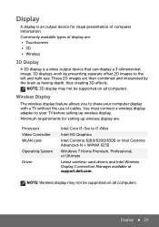
...2D images to share your TV before setting up wireless display. These 2D images are : • Touchscreen • 3D • Wireless 3D Display A 3D display is an output device for setting up wireless display are: Processor Video Controller WLAN card Operating System Driver Intel...connect a wireless display adapter to i7-66xx Intel HD Graphics Intel Centrino 6100/6200/6300 or Intel Centrino Advanced-N + WiMAX 6250 Windows 7 Home Premium, Professional, or Ultimate Latest wireless-card drivers and Intel Wireless Display Connection Manager available at support.dell.com. Minimum ...
...2D images to share your TV before setting up wireless display. These 2D images are : • Touchscreen • 3D • Wireless 3D Display A 3D display is an output device for setting up wireless display are: Processor Video Controller WLAN card Operating System Driver Intel...connect a wireless display adapter to i7-66xx Intel HD Graphics Intel Centrino 6100/6200/6300 or Intel Centrino Advanced-N + WiMAX 6250 Windows 7 Home Premium, Professional, or Ultimate Latest wireless-card drivers and Intel Wireless Display Connection Manager available at support.dell.com. Minimum ...
Me and My Dell
Page 61
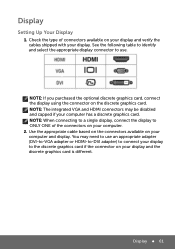
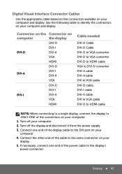
... connectors available on your computer has a discrete graphics card. Display 61 Check the type of the connectors on your display and verify the cables shipped with your computer. 2. NOTE: When connecting to a single display, connect the display to ONLY ONE of connectors available on your display. You may be disabled and capped if your computer...
... connectors available on your computer has a discrete graphics card. Display 61 Check the type of the connectors on your display and verify the cables shipped with your computer. 2. NOTE: When connecting to a single display, connect the display to ONLY ONE of connectors available on your display. You may be disabled and capped if your computer...
Me and My Dell
Page 62
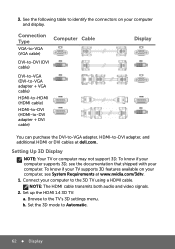
...with your computer to Automatic. 62 Display Connection Type VGA-to-VGA (VGA cable) Computer Cable DVI-to-DVI (DVI cable) DVI-to-VGA (DVI-to-VGA adapter + VGA cable) HDMI-to-HDMI (HDMI cable) HDMI-to-DVI (HDMI-to-DVI adapter + DVI cable) Display You can purchase the DVI-to-VGA adapter,...the HDMI 1.4 3D TV: a. Set the 3D mode to the 3D TV using a HDMI cable. To know if your TV supports 3D features available on your computer supports 3D, see System Requirements at dell.com. To know if your computer and display. Browse to -DVI adapter, and additional HDMI or DVI...
...with your computer to Automatic. 62 Display Connection Type VGA-to-VGA (VGA cable) Computer Cable DVI-to-DVI (DVI cable) DVI-to-VGA (DVI-to-VGA adapter + VGA cable) HDMI-to-HDMI (HDMI cable) HDMI-to-DVI (HDMI-to-DVI adapter + DVI cable) Display You can purchase the DVI-to-VGA adapter,...the HDMI 1.4 3D TV: a. Set the 3D mode to the 3D TV using a HDMI cable. To know if your TV supports 3D features available on your computer supports 3D, see System Requirements at dell.com. To know if your computer and display. Browse to -DVI adapter, and additional HDMI or DVI...
Me and My Dell
Page 65
... the same connector on your computer and display. Turn off your computer. 1. Turn off the display and disconnect it from the power supply. 3. Connect the other end of the display cable to the display's power connector. If necessary, connect one end of the cable to identify the connectors on your display. 5. Display 65 Connect one end of...
... the same connector on your computer and display. Turn off your computer. 1. Turn off the display and disconnect it from the power supply. 3. Connect the other end of the display cable to the display's power connector. If necessary, connect one end of the cable to identify the connectors on your display. 5. Display 65 Connect one end of...

Me and My Dell
Page 66
Connect the other end of the power cable to the display's three-prong power strip or wall outlet. 7. Turn on your computer, and then turn on your display. Audio Setting Up 5.1 Audio 5.1 audio is most effective when the speakers are placed as shown in the following figure: 66 Audio 6.
Connect the other end of the power cable to the display's three-prong power strip or wall outlet. 7. Turn on your computer, and then turn on your display. Audio Setting Up 5.1 Audio 5.1 audio is most effective when the speakers are placed as shown in the following figure: 66 Audio 6.
Me and My Dell
Page 71
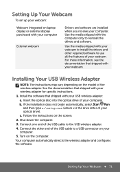
... 1. Install the software that shipped with the computer only to the USB wireless adapter. 4. Follow the instructions on laptop display or external display purchased with your webcam to a USB connector on the computer. Turn on your computer. Installing Your USB Wireless Adapter NOTE:...media shipped with your computer. Shut down the computer. 3. Connect the other required software to use all the features of the USB cable to reinstall the drivers and software. Setting Up Your Webcam 71 b. c. For more information, see the documentation that shipped ...
... 1. Install the software that shipped with the computer only to the USB wireless adapter. 4. Follow the instructions on laptop display or external display purchased with your webcam to a USB connector on the computer. Turn on your computer. Installing Your USB Wireless Adapter NOTE:...media shipped with your computer. Shut down the computer. 3. Connect the other required software to use all the features of the USB cable to reinstall the drivers and software. Setting Up Your Webcam 71 b. c. For more information, see the documentation that shipped ...


