
Service Manual
Page 3
......6 Safety instructions...6 Electrostatic discharge-ESD protection...7 ESD field service kit ...7 Transporting sensitive components...8 Entering Service Mode...8 After working inside your computer...9 Exiting Service Mode...9 Chapter 2: Removing and installing components 10 Recommended tools...10 Screw list...10 Major components of Inspiron 5410 2-in-1...11 Base cover...13 Removing the base cover...13 Installing the base cover...15 Battery...16 Lithium-ion battery precautions...16 Removing the 3-cell or 4-cell battery...16 Installing the 3-cell...
......6 Safety instructions...6 Electrostatic discharge-ESD protection...7 ESD field service kit ...7 Transporting sensitive components...8 Entering Service Mode...8 After working inside your computer...9 Exiting Service Mode...9 Chapter 2: Removing and installing components 10 Recommended tools...10 Screw list...10 Major components of Inspiron 5410 2-in-1...11 Base cover...13 Removing the base cover...13 Installing the base cover...15 Battery...16 Lithium-ion battery precautions...16 Removing the 3-cell or 4-cell battery...16 Installing the 3-cell...

Service Manual
Page 4
... Intel Virtual Button driver...61 Wireless and Bluetooth drivers...61 Chapter 4: System setup...62 BIOS overview...62 Entering BIOS setup program...62 Navigation keys...62 Boot Sequence...62 One time boot menu...63 System setup options...63 System and setup password...72 Assigning a system setup password...72 Deleting or changing an existing system setup password 73 Clearing CMOS settings...73 Clearing BIOS (System Setup) and System passwords 74 Chapter 5: Troubleshooting...75 SupportAssist diagnostics...75 Locate the Service Tag or Express Service Code of your Dell computer...
... Intel Virtual Button driver...61 Wireless and Bluetooth drivers...61 Chapter 4: System setup...62 BIOS overview...62 Entering BIOS setup program...62 Navigation keys...62 Boot Sequence...62 One time boot menu...63 System setup options...63 System and setup password...72 Assigning a system setup password...72 Deleting or changing an existing system setup password 73 Clearing CMOS settings...73 Clearing BIOS (System Setup) and System passwords 74 Chapter 5: Troubleshooting...75 SupportAssist diagnostics...75 Locate the Service Tag or Express Service Code of your Dell computer...

Service Manual
Page 6
... applicable. Remove any media card and optical disc from your computer and then unplug the cable from the network device. 5. CAUTION: To avoid damaging the components and cards, handle them by the Dell technical assistance team. Disconnect your computer. CAUTION: You should only perform troubleshooting and repairs as keyboard, mouse, and monitor from your computer and all attached devices from their edges, and avoid touching the...
... applicable. Remove any media card and optical disc from your computer and then unplug the cable from the network device. 5. CAUTION: To avoid damaging the components and cards, handle them by the Dell technical assistance team. Disconnect your computer. CAUTION: You should only perform troubleshooting and repairs as keyboard, mouse, and monitor from your computer and all attached devices from their edges, and avoid touching the...

Service Manual
Page 8
... the new part arrived in anti-static bags for a desktop or portable environment. Entering Service Mode Service Mode allows users to immediately cut off electricity from the computer and conduct repairs without disconnecting the battery cable from normal wear and tear, and must be checked regularly with your back. 4. Always be aware that technicians keep ESD sensitive devices, such as replacement parts or parts to...
... the new part arrived in anti-static bags for a desktop or portable environment. Entering Service Mode Service Mode allows users to immediately cut off electricity from the computer and conduct repairs without disconnecting the battery cable from normal wear and tear, and must be checked regularly with your back. 4. Always be aware that technicians keep ESD sensitive devices, such as replacement parts or parts to...

Service Manual
Page 9
... enter Service Mode: 1. Once the computer shuts down, you removed before working on your computer. 2. Press the power button to normal functioning mode. Your computer will automatically return to turn on your computer. 2. Remove the AC adapter and then press any key to continue. Replace any media cards, discs, or any key to immediately cut off electricity from the computer and conduct repairs without disconnecting the battery cable from the system board. Connect...
... enter Service Mode: 1. Once the computer shuts down, you removed before working on your computer. 2. Press the power button to normal functioning mode. Your computer will automatically return to turn on your computer. 2. Remove the AC adapter and then press any key to continue. Replace any media cards, discs, or any key to immediately cut off electricity from the computer and conduct repairs without disconnecting the battery cable from the system board. Connect...

Service Manual
Page 20
... 1. Enter Service Mode. It is equivalent to removing the coin-cell battery. About this task The following image indicates the location of the coin-cell battery and provides a visual representation of the removal procedure. 20 Removing and installing components Using the alignment posts, place the battery on the palm-rest and keyboard assembly. 2. Next steps 1. It resets the BIOS setup program's settings to the system board. 4. Install the base cover. 2. Steps 1. Connect...
... 1. Enter Service Mode. It is equivalent to removing the coin-cell battery. About this task The following image indicates the location of the coin-cell battery and provides a visual representation of the removal procedure. 20 Removing and installing components Using the alignment posts, place the battery on the palm-rest and keyboard assembly. 2. Next steps 1. It resets the BIOS setup program's settings to the system board. 4. Install the base cover. 2. Steps 1. Connect...

Service Manual
Page 51
... the power button with the optional fingerprint-reader cable, on your computer. 6. Next steps 1. Install the display assembly. 3. Remove the base cover. 3. Remove the battery. 4. Replace the two screws (M1.6x2) that secure power button to the palm-rest and keyboard assembly. System board Removing the system board Prerequisites 1. About this task The following image indicates the connectors on the slot of the palm-rest and keyboard assembly. 2. Exit Service Mode. Install the I/O board. 2. Install the fan. 4. Install...
... the power button with the optional fingerprint-reader cable, on your computer. 6. Next steps 1. Install the display assembly. 3. Remove the base cover. 3. Remove the battery. 4. Replace the two screws (M1.6x2) that secure power button to the palm-rest and keyboard assembly. System board Removing the system board Prerequisites 1. About this task The following image indicates the connectors on the slot of the palm-rest and keyboard assembly. 2. Exit Service Mode. Install the I/O board. 2. Install the fan. 4. Install...

Service Manual
Page 57
... secures the USB Type-C port bracket to secure the cable. 4. Connect the power-adapter port cable to the system board. 5. Connect the keyboard cable to the connector on the system board. 6. Install the fan. 2. Connect the speaker cable to secure the cable. 8. Connect the I /O-board cable to the system board. 16. Install the heat sink. 3. Install the memory modules. Connect the touchpad cable to the connector on the system board and close the latch to the system board. 10. Install the wireless card. 5. Replace the two...
... secures the USB Type-C port bracket to secure the cable. 4. Connect the power-adapter port cable to the system board. 5. Connect the keyboard cable to the connector on the system board. 6. Install the fan. 2. Connect the speaker cable to secure the cable. 8. Connect the I /O-board cable to the system board. 16. Install the heat sink. 3. Install the memory modules. Connect the touchpad cable to the connector on the system board and close the latch to the system board. 10. Install the wireless card. 5. Replace the two...

Service Manual
Page 58
... keyboard assembly and provides a visual representation of the removal procedure. 58 Removing and installing components 6. Remove the power-adapter port. 14. Remove the power button with the heat sink. Remove the display assembly. 16. NOTE: The system board can be removed along with optional fingerprint reader. 15. Follow the procedure in Before working inside your computer. Remove the coin-cell battery. 5. Remove the memory modules. 6. Remove the heat sink. 11. Remove the battery. 4. Install the battery. 7. Install the base cover. 8. Remove the wireless card...
... keyboard assembly and provides a visual representation of the removal procedure. 58 Removing and installing components 6. Remove the power-adapter port. 14. Remove the power button with the heat sink. Remove the display assembly. 16. NOTE: The system board can be removed along with optional fingerprint reader. 15. Follow the procedure in Before working inside your computer. Remove the coin-cell battery. 5. Remove the memory modules. 6. Remove the heat sink. 11. Remove the battery. 4. Install the battery. 7. Install the base cover. 8. Remove the wireless card...
Service Manual
Page 61
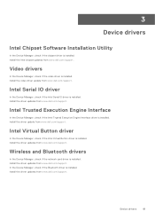
...the network card driver is installed. Install the driver updates from www.dell.com/support. Install the Intel chipset updates from www.dell.com/support. Install the driver updates from www.dell.com/support. Intel Serial IO driver In the Device Manager, check if the Intel Serial IO driver is installed. Intel Virtual Button driver In the Device Manager, check if the Intel Virtual Button driver is installed. Device drivers 61 Install the driver updates from www.dell.com/support. In the Device Manager, check if the Bluetooth driver is installed. 3 Device drivers Intel...
...the network card driver is installed. Install the driver updates from www.dell.com/support. Install the Intel chipset updates from www.dell.com/support. Install the driver updates from www.dell.com/support. Intel Serial IO driver In the Device Manager, check if the Intel Serial IO driver is installed. Intel Virtual Button driver In the Device Manager, check if the Intel Virtual Button driver is installed. Device drivers 61 Install the driver updates from www.dell.com/support. In the Device Manager, check if the Bluetooth driver is installed. 3 Device drivers Intel...
Service Manual
Page 62
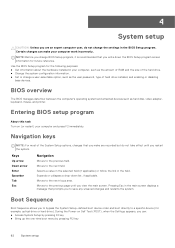
... hard drive installed, and enabling or disabling base devices. Moves to the next field. Keys Up arrow Down arrow Enter Spacebar Tab Esc Navigation Moves to the previous page until you restart the system. BIOS overview The BIOS manages data flow between the computer's operating system and attached devices such as the user password, type of the hard drive. ● Change the system configuration information. ● Set or change a user-selectable option, such as hard disk, video adapter, keyboard, mouse...
... hard drive installed, and enabling or disabling base devices. Moves to the next field. Keys Up arrow Down arrow Enter Spacebar Tab Esc Navigation Moves to the previous page until you restart the system. BIOS overview The BIOS manages data flow between the computer's operating system and attached devices such as the user password, type of the hard drive. ● Change the system configuration information. ● Set or change a user-selectable option, such as hard disk, video adapter, keyboard, mouse...

Service Manual
Page 64
... the boot mode of the computer. Processor L3 Cache Displays the processor L3 Cache size. Video Controller Displays the integrate graphics information of the computer. Bluetooth Device Displays whether a Bluetooth device is selected Secure Boot Enable Secure Boot Secure Boot Mode Expert Key Management Enables secure boot using only validated boot software. By default, Windows Boot Manager is selected By default, UEFI Hard Drive is installed in the computer. Enables or disables Windows Boot Manager and UEFI Hard Drive. DEVICES Panel Type Displays the Panel Type...
... the boot mode of the computer. Processor L3 Cache Displays the processor L3 Cache size. Video Controller Displays the integrate graphics information of the computer. Bluetooth Device Displays whether a Bluetooth device is selected Secure Boot Enable Secure Boot Secure Boot Mode Expert Key Management Enables secure boot using only validated boot software. By default, Windows Boot Manager is selected By default, UEFI Hard Drive is installed in the computer. Enables or disables Windows Boot Manager and UEFI Hard Drive. DEVICES Panel Type Displays the Panel Type...

Service Manual
Page 66
...-Connection menu Connection Wireless Device Enable WLAN Enable or disable internal WLAN devices. Enable UEFI Network Stack Enable UEFI Network Stack Enables or disables UEFI networking protocols, if they are installed and available. Default: ON HTTP(s) Boot Feature When the Certificate is running on AC power Sets the screen brightness when the computer is displayed if the image matches the screen resolution. System setup options-Display menu Display Display Brightness Brightness on battery during power usage hours. Use the below options to run on battery power Sets...
...-Connection menu Connection Wireless Device Enable WLAN Enable or disable internal WLAN devices. Enable UEFI Network Stack Enable UEFI Network Stack Enables or disables UEFI networking protocols, if they are installed and available. Default: ON HTTP(s) Boot Feature When the Certificate is running on AC power Sets the screen brightness when the computer is displayed if the image matches the screen resolution. System setup options-Display menu Display Display Brightness Brightness on battery during power usage hours. Use the below options to run on battery power Sets...
Service Manual
Page 67
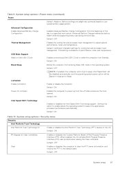
... adjust system performance, noise, and temperature. Default: Optimized. This setting is opened. Default: ON Table 10. Advanced Battery Charged maximizes battery health while still supporting heavy use during the work period. Default: ON Intel Speed Shift Technology Enables or disables the Intel Speed Shift Technology support. When enabled, the OS will be disabled automatically, and the operating system power option will skip BIOS Physical Presence Interface (PPI) user prompts when issuing the Clear...
... adjust system performance, noise, and temperature. Default: Optimized. This setting is opened. Default: ON Table 10. Advanced Battery Charged maximizes battery health while still supporting heavy use during the work period. Default: ON Intel Speed Shift Technology Enables or disables the Intel Speed Shift Technology support. When enabled, the OS will be disabled automatically, and the operating system power option will skip BIOS Physical Presence Interface (PPI) user prompts when issuing the Clear...

Service Manual
Page 68
.... Default: Disabled Password Changes Enable Non-Admin Password Changes Enables or disables the user to the system board on Next Boot When enabled, the BIOS will prompt the user to enter the admin password (if set) when booting to set, change , or delete the system password. Default: ON 68 System setup Default: Enabled Determines if the system will schedule a data wipe cycle for all storage devices connected to change , or delete the NVMe SSD0 password. Default: Always Except Internal HDD. System setup options-Passwords menu Passwords Admin Password Enables you...
.... Default: Disabled Password Changes Enable Non-Admin Password Changes Enables or disables the user to the system board on Next Boot When enabled, the BIOS will prompt the user to enter the admin password (if set) when booting to set, change , or delete the system password. Default: ON 68 System setup Default: Enabled Determines if the system will schedule a data wipe cycle for all storage devices connected to change , or delete the NVMe SSD0 password. Default: Always Except Internal HDD. System setup options-Passwords menu Passwords Admin Password Enables you...

Service Manual
Page 69
... options-Update,Recovery menu Wireless UEFI Capsule Firmware Updates Enable UEFI Capsule Firmware Updates Enables or disables BIOS updates through UEFI capsule update packages. Default: OFF Table 12. Default: ON SupportAssist OS Recovery Enables or disables the boot flow for Dell operating system Recovery tool. System setup options-Passwords menu Passwords Admin Setup Lockout Enable Admin Setup Lockout Enables or disables the user from a bad BIOS image, as long as the Boot Block portion is set. Default: ON NOTE: BIOS recovery is designed to recover from entering BIOS...
... options-Update,Recovery menu Wireless UEFI Capsule Firmware Updates Enable UEFI Capsule Firmware Updates Enables or disables BIOS updates through UEFI capsule update packages. Default: OFF Table 12. Default: ON SupportAssist OS Recovery Enables or disables the boot flow for Dell operating system Recovery tool. System setup options-Passwords menu Passwords Admin Setup Lockout Enable Admin Setup Lockout Enables or disables the user from a bad BIOS image, as long as the Boot Block portion is set. Default: ON NOTE: BIOS recovery is designed to recover from entering BIOS...

Service Manual
Page 70
... Wake on Battery Enables the user to the device. Table 13. System setup options-System Management menu System Management Service Tag Displays the Service Tag of function keys F1-F12. Once set . Stop, prompt, and wait for Admin password. 70 System setup Asset Tag Creates a system Asset Tag that can be changed. System setup options-Keyboard menu Keyboard Numlock Enable Enable Numlock Enables or disables Numlock when the computer boots. Default: ON Fn Lock Options Enables or disables the Fn lock mode. Default: Lock Mode Secondary Keyboard Illumination Enables the user to...
... Wake on Battery Enables the user to the device. Table 13. System setup options-System Management menu System Management Service Tag Displays the Service Tag of function keys F1-F12. Once set . Stop, prompt, and wait for Admin password. 70 System setup Asset Tag Creates a system Asset Tag that can be changed. System setup options-Keyboard menu Keyboard Numlock Enable Enable Numlock Enables or disables Numlock when the computer boots. Default: ON Fn Lock Options Enables or disables the Fn lock mode. Default: Lock Mode Secondary Keyboard Illumination Enables the user to...

Service Manual
Page 73
... existing System and Setup password. Remove the base cover. Turn on or reboot. Type the system password that the Password Status is Unlocked. 3. Deleting or changing an existing system setup password Prerequisites Ensure that you delete the System and Setup password, confirm the deletion when prompted. 5. About this task CAUTION: Clearing CMOS settings will reset the BIOS settings on your computer. Select System/Admin Password and create a password in Removing the base cover). 3. Steps 1. The computer...
... existing System and Setup password. Remove the base cover. Turn on or reboot. Type the system password that the Password Status is Unlocked. 3. Deleting or changing an existing system setup password Prerequisites Ensure that you delete the System and Setup password, confirm the deletion when prompted. 5. About this task CAUTION: Clearing CMOS settings will reset the BIOS settings on your computer. Select System/Admin Password and create a password in Removing the base cover). 3. Steps 1. The computer...
Service Manual
Page 77
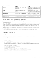
.... Indicates a problem with Windows 10 operating system. Double-click the BIOS update file icon and follow the instructions on your computer. 2. It enables you replace the system board. Click Product support, enter the Service Tag of tools to diagnose and troubleshoot issues that is supplying power to software or hardware failures. Troubleshooting 77 Flashing the BIOS About this task You may occur before your computer when it automatically starts Dell SupportAssist OS Recovery...
.... Indicates a problem with Windows 10 operating system. Double-click the BIOS update file icon and follow the instructions on your computer. 2. It enables you replace the system board. Click Product support, enter the Service Tag of tools to diagnose and troubleshoot issues that is supplying power to software or hardware failures. Troubleshooting 77 Flashing the BIOS About this task You may occur before your computer when it automatically starts Dell SupportAssist OS Recovery...

Service Manual
Page 78
... wireless router. 4. To drain residual flea power (perform a hard reset) Steps 1. Backup media and recovery options It is removed. Flashing BIOS (USB key) Steps 1. Dell proposes multiple options for 30 seconds. 5. Follow the procedure from step 1 to step 7 in your computer is displayed on the screen to the USB drive from your computer. 2. Create a bootable USB drive. For more information. Connect the bootable USB drive to troubleshoot and fix problems that needs the BIOS update. 5. Type the BIOS setup program filename and press Enter. 8. The BIOS Update Utility...
... wireless router. 4. To drain residual flea power (perform a hard reset) Steps 1. Backup media and recovery options It is removed. Flashing BIOS (USB key) Steps 1. Dell proposes multiple options for 30 seconds. 5. Follow the procedure from step 1 to step 7 in your computer is displayed on the screen to the USB drive from your computer. 2. Create a bootable USB drive. For more information. Connect the bootable USB drive to troubleshoot and fix problems that needs the BIOS update. 5. Type the BIOS setup program filename and press Enter. 8. The BIOS Update Utility...


