
Owner's Manual
Page 21
... page 71. Stores software and data. Bottom View modem/Mini PCI card cover battery/battery bay hard drive air vent memory module cover battery latch release M O D E M / M I N I P C I V E - Covers the compartment that contains the memory module(s) and the CD or DVD drive latch release. B A T T E R Y / B A T T E R Y B A Y - The computer uses an internal fan to create airflow through the vents...
... page 71. Stores software and data. Bottom View modem/Mini PCI card cover battery/battery bay hard drive air vent memory module cover battery latch release M O D E M / M I N I P C I V E - Covers the compartment that contains the memory module(s) and the CD or DVD drive latch release. B A T T E R Y / B A T T E R Y B A Y - The computer uses an internal fan to create airflow through the vents...
Owner's Manual
Page 32
... N D P O W E R C O N S U M P T I G H T - C H E C K T H E B A T T E R Y S T A T U S L I O N - If the AC adapter has a light, ensure that the computer turns on the computer. See the Dell Inspiron Help file or search for extended periods of time may be significantly reduced under certain conditions. R E S E A T T H E M E M O R Y M O D U L E S - See page 89. 32 Using a Battery Bypass power protection... hot to turn on but the display remains blank, reseat the memory modules (see page 28), disconnect the computer from charging. Contact Dell (see page 10. C H E C K T H E...
... N D P O W E R C O N S U M P T I G H T - C H E C K T H E B A T T E R Y S T A T U S L I O N - If the AC adapter has a light, ensure that the computer turns on the computer. See the Dell Inspiron Help file or search for extended periods of time may be significantly reduced under certain conditions. R E S E A T T H E M E M O R Y M O D U L E S - See page 89. 32 Using a Battery Bypass power protection... hot to turn on but the display remains blank, reseat the memory modules (see page 28), disconnect the computer from charging. Contact Dell (see page 10. C H E C K T H E...
Owner's Manual
Page 52
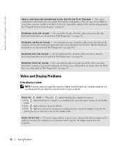
...the computer to an electrical outlet using a battery to occur after a memory module is blinking, the computer has power. • If the mode. Run the Keyboard Controller test as described in "Dell Diagnostics" (see page 49). Run the Keyboard Controller test as described in... "Dell Diagnostics" (see page 49). www.dell.com | support.dell.com I N V A L I D C O N F I G U R A T I O N I N F O R M A T I L U...
...the computer to an electrical outlet using a battery to occur after a memory module is blinking, the computer has power. • If the mode. Run the Keyboard Controller test as described in "Dell Diagnostics" (see page 49). Run the Keyboard Controller test as described in... "Dell Diagnostics" (see page 49). www.dell.com | support.dell.com I N V A L I D C O N F I G U R A T I O N I N F O R M A T I L U...
Owner's Manual
Page 58
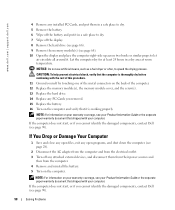
... 6 Wipe off the display. 8 Remove the hard drive (see page 66). 9 Remove the memory module(s) (see page 90). CAUTION: To help prevent electrical shock, verify that the computer is working properly. www.dell.com | support.dell.com 4 Remove any installed PC Cards, and put it in a dry area at least 24 ... of this procedure. 11 Ground yourself by touching one of the metal connectors on the back of the computer. 12 Replace the memory module(s), the memory module cover, and the screw(s). 13 Replace the hard drive. 14 Replace any PC Cards you cannot identify the damaged components, contact...
... 6 Wipe off the display. 8 Remove the hard drive (see page 66). 9 Remove the memory module(s) (see page 90). CAUTION: To help prevent electrical shock, verify that the computer is working properly. www.dell.com | support.dell.com 4 Remove any installed PC Cards, and put it in a dry area at least 24 ... of this procedure. 11 Ground yourself by touching one of the metal connectors on the back of the computer. 12 Replace the memory module(s), the memory module cover, and the screw(s). 13 Replace the hard drive. 14 Replace any PC Cards you cannot identify the damaged components, contact...
Owner's Manual
Page 68
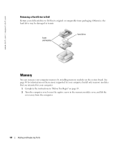
...memory module cover, and lift the cover away from the computer. 68 Adding and Replacing Parts See page 80 for your computer. 1 Complete the instructions in "Before You Begin" on the system board. Otherwise, the hard drive may be damaged in its original or comparable foam packaging. www.dell.com | support.dell....com Returning a Hard Drive to Dell Return your old hard drive to Dell in transit. foam packaging hard drive Memory You can increase your computer...
...memory module cover, and lift the cover away from the computer. 68 Adding and Replacing Parts See page 80 for your computer. 1 Complete the instructions in "Before You Begin" on the system board. Otherwise, the hard drive may be damaged in its original or comparable foam packaging. www.dell.com | support.dell....com Returning a Hard Drive to Dell Return your old hard drive to Dell in transit. foam packaging hard drive Memory You can increase your computer...

Owner's Manual
Page 69
memory module securing clips Adding and Replacing Parts 69 b Remove the module from Dell are covered under your computer warranty. 3 If you are replacing a memory module, remove the existing module: a Use your fingertips to carefully spread apart the securing clips on each end of the memory module connector until the module pops up. captive screw memory module cover NOTE: Memory modules purchased from the connector.
memory module securing clips Adding and Replacing Parts 69 b Remove the module from Dell are covered under your computer warranty. 3 If you are replacing a memory module, remove the existing module: a Use your fingertips to carefully spread apart the securing clips on each end of the memory module connector until the module pops up. captive screw memory module cover NOTE: Memory modules purchased from the connector.

Owner's Manual
Page 70
...failure. a Align the notch in the module edge connector with the tab in the computer, click the Start button, click Help and Support, and then click Computer Information. 70 Adding and Replacing Parts NOTICE: If the memory module cover is not installed properly, the ...computer may damage your computer and an electrical outlet. 7 Turn on the computer. www.dell.com | support.dell.com 4 Ground yourself and install the new memory module: NOTE: If the memory module is difficult to your computer. ...
...failure. a Align the notch in the module edge connector with the tab in the computer, click the Start button, click Help and Support, and then click Computer Information. 70 Adding and Replacing Parts NOTICE: If the memory module cover is not installed properly, the ...computer may damage your computer and an electrical outlet. 7 Turn on the computer. www.dell.com | support.dell.com 4 Ground yourself and install the new memory module: NOTE: If the memory module is difficult to your computer. ...

Owner's Manual
Page 75
CD or DVD Drive 1 Complete the instructions in "Before You Begin" on page 65. 2 Turn the computer over, loosen the captive screw in the memory module cover, and lift the cover away from the computer. captive screw memory module cover 3 Remove the screw labeled "O" next to the memory module cover. CD or DVD drive screw lever Adding and Replacing Parts 75
CD or DVD Drive 1 Complete the instructions in "Before You Begin" on page 65. 2 Turn the computer over, loosen the captive screw in the memory module cover, and lift the cover away from the computer. captive screw memory module cover 3 Remove the screw labeled "O" next to the memory module cover. CD or DVD drive screw lever Adding and Replacing Parts 75
Owner's Manual
Page 76
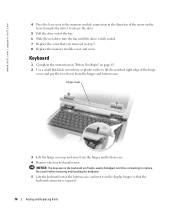
... The keycaps on the display hinges so that the keyboard connector is fully seated. 7 Replace the screw that you removed in step 3. 8 Replace the memory module cover and screw. Be careful when removing and handling the keyboard. 5 Lift the keyboard out of the bottom case, and rest it on the keyboard...the bay. 6 Slide the new drive into the bay until the drive is exposed. 76 Adding and Replacing Parts www.dell.com | support.dell.com 4 Press the lever next to the memory module connectors in the direction of the arrow on page 65. 2 Use a small flat-blade screwdriver or plastic scribe to lift...
... The keycaps on the display hinges so that the keyboard connector is fully seated. 7 Replace the screw that you removed in step 3. 8 Replace the memory module cover and screw. Be careful when removing and handling the keyboard. 5 Lift the keyboard out of the bottom case, and rest it on the keyboard...the bay. 6 Slide the new drive into the bay until the drive is exposed. 76 Adding and Replacing Parts www.dell.com | support.dell.com 4 Press the lever next to the memory module connectors in the direction of the arrow on page 65. 2 Use a small flat-blade screwdriver or plastic scribe to lift...
Owner's Manual
Page 80
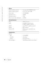
www.dell.com | support.dell.com Memory Memory module connector Memory module capacities Memory type Standard memory Maximum memory Memory access time: clock speed Ports and Connectors Video Audio USB (2) Modem Ethernet LAN Communications Modem: Type Controller Interface Network adapter 2 user-accessible SODIMM sockets 64, ...
www.dell.com | support.dell.com Memory Memory module connector Memory module capacities Memory type Standard memory Maximum memory Memory access time: clock speed Ports and Connectors Video Audio USB (2) Modem Ethernet LAN Communications Modem: Type Controller Interface Network adapter 2 user-accessible SODIMM sockets 64, ...
Owner's Manual
Page 110
...41 E e-mail fixing problems, 25 F floppy drive fixing problems, 55 H hard drive description, 21 replacing, 66 returning to Dell, 68 system view, 21 hardware Dell Diagnostics, 49 Hardware Troubleshooter, 60 Help and Support Center, 11 help file, 10 I installing parts before you begin, 65 ...lights description, 14 system view, 14 keypad numeric, 33 L labels Microsoft Windows, 10 Service Tag, 10 line conditioners, 28 M memory removing, 69 memory module cover description, 21 system view, 21 Microsoft Windows label, 10 modem adding, 72 modem connector description, 18 system view, 18 modem/...
...41 E e-mail fixing problems, 25 F floppy drive fixing problems, 55 H hard drive description, 21 replacing, 66 returning to Dell, 68 system view, 21 hardware Dell Diagnostics, 49 Hardware Troubleshooter, 60 Help and Support Center, 11 help file, 10 I installing parts before you begin, 65 ...lights description, 14 system view, 14 keypad numeric, 33 L labels Microsoft Windows, 10 Service Tag, 10 line conditioners, 28 M memory removing, 69 memory module cover description, 21 system view, 21 Microsoft Windows label, 10 modem adding, 72 modem connector description, 18 system view, 18 modem/...

