Owners Manual
Page 3
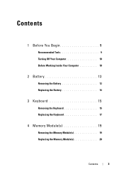
Contents 1 Before You Begin 9 Recommended Tools 9 Turning Off Your Computer 10 Before Working Inside Your Computer 10 2 Battery 13 Removing the Battery 13 Replacing the Battery 14 3 Keyboard 15 Removing the Keyboard 15 Replacing the Keyboard 17 4 Memory Module(s 19 Removing the Memory Module(s 19 Replacing the Memory Module(s 20 Contents 3
Contents 1 Before You Begin 9 Recommended Tools 9 Turning Off Your Computer 10 Before Working Inside Your Computer 10 2 Battery 13 Removing the Battery 13 Replacing the Battery 14 3 Keyboard 15 Removing the Keyboard 15 Replacing the Keyboard 17 4 Memory Module(s 19 Removing the Memory Module(s 19 Replacing the Memory Module(s 20 Contents 3
Owners Manual
Page 5
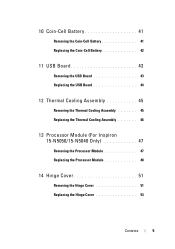
10 Coin-Cell Battery 41 Removing the Coin-Cell Battery 41 Replacing the Coin-Cell Battery 42 11 USB Board 43 Removing the USB Board 43 Replacing the USB Board 44 12 Thermal Cooling Assembly 45 Removing the Thermal Cooling Assembly 45 Replacing the Thermal Cooling Assembly 46 13 Processor Module (For Inspiron 15-N5050/15-N5040 Only 47 Removing the Processor Module 47 Replacing the Processor Module 48 14 Hinge Cover 51 Removing the Hinge Cover 51 Replacing the Hinge Cover 53 Contents 5
10 Coin-Cell Battery 41 Removing the Coin-Cell Battery 41 Replacing the Coin-Cell Battery 42 11 USB Board 43 Removing the USB Board 43 Replacing the USB Board 44 12 Thermal Cooling Assembly 45 Removing the Thermal Cooling Assembly 45 Replacing the Thermal Cooling Assembly 46 13 Processor Module (For Inspiron 15-N5050/15-N5040 Only 47 Removing the Processor Module 47 Replacing the Processor Module 48 14 Hinge Cover 51 Removing the Hinge Cover 51 Replacing the Hinge Cover 53 Contents 5
Owners Manual
Page 6
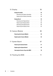
15 Display 55 Display Assembly 55 Removing the Display Assembly 55 Replacing the Display Assembly 58 Display Bezel 59 Removing the Display Bezel 59 Replacing the Display Bezel 60 Removing the Display Panel 60 Replacing the Display Panel 63 16 Camera Module 65 Removing the Camera Module 65 Replacing the Camera Module 66 17 System Board 67 Removing the System Board 67 Replacing the System Board 69 Entering the Service Tag in the BIOS 70 18 Flashing the BIOS 71 6 Contents
15 Display 55 Display Assembly 55 Removing the Display Assembly 55 Replacing the Display Assembly 58 Display Bezel 59 Removing the Display Bezel 59 Replacing the Display Bezel 60 Removing the Display Panel 60 Replacing the Display Panel 63 16 Camera Module 65 Removing the Camera Module 65 Replacing the Camera Module 66 17 System Board 67 Removing the System Board 67 Replacing the System Board 69 Entering the Service Tag in the BIOS 70 18 Flashing the BIOS 71 6 Contents
Owners Manual
Page 11
..., open the display, and press the power button to prevent the computer cover from your computer. Also, before you disconnect the cable. See "Turning Off Your Computer" on the locking tabs before you connect a cable, ensure that both connectors are disconnecting this type of cable, press in -1 media card reader. 5 Disconnect your computer and all attached devices from their electrical outlets. 6 Disconnect all attached devices. See "Removing the Battery...
..., open the display, and press the power button to prevent the computer cover from your computer. Also, before you disconnect the cable. See "Turning Off Your Computer" on the locking tabs before you connect a cable, ensure that both connectors are disconnecting this type of cable, press in -1 media card reader. 5 Disconnect your computer and all attached devices from their electrical outlets. 6 Disconnect all attached devices. See "Removing the Battery...
Owners Manual
Page 15
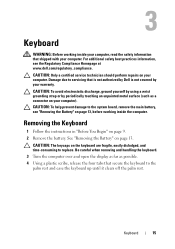
... to replace. CAUTION: The keycaps on page 9. 2 Remove the battery. Damage due to servicing that is not authorized by Dell is not covered by periodically touching an unpainted metal surface (such as possible. 4 Using a plastic scribe, release the four tabs that secure the keyboard to the system board, remove the main battery, see the Regulatory Compliance Homepage at www.dell.com/regulatory_compliance. Keyboard 15 For...
... to replace. CAUTION: The keycaps on page 9. 2 Remove the battery. Damage due to servicing that is not authorized by Dell is not covered by periodically touching an unpainted metal surface (such as possible. 4 Using a plastic scribe, release the four tabs that secure the keyboard to the system board, remove the main battery, see the Regulatory Compliance Homepage at www.dell.com/regulatory_compliance. Keyboard 15 For...
Owners Manual
Page 19
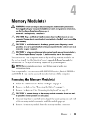
... on the type of the computer. See "Removing the Battery" on page 15. CAUTION: To avoid electrostatic discharge, ground yourself by using a wrist grounding strap or by installing memory modules on page 13, before working inside the computer. See "Removing the Keyboard" on page 13. 3 Remove the keyboard. You can be accessed from the bottom of memory supported by your computer warranty. Removing the Memory Module(s) 1 Follow the instructions in...
... on the type of the computer. See "Removing the Battery" on page 15. CAUTION: To avoid electrostatic discharge, ground yourself by using a wrist grounding strap or by installing memory modules on page 13, before working inside the computer. See "Removing the Keyboard" on page 13. 3 Remove the keyboard. You can be accessed from the bottom of memory supported by your computer warranty. Removing the Memory Module(s) 1 Follow the instructions in...
Owners Manual
Page 20
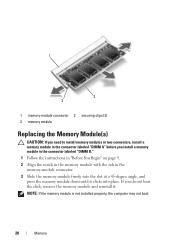
... hear the click, remove the memory module and reinstall it clicks into place. NOTE: If the memory module is not installed properly, the computer may not boot. 20 Memory 1 3 2 1 memory-module connector 2 securing clips (2) 3 memory module Replacing the Memory Module(s) CAUTION: If you need to install memory modules in two connectors, install a memory module in the memory-module connector. 3 Slide the memory module firmly into the slot at a 45-degree angle, and press the memory module down until it...
... hear the click, remove the memory module and reinstall it clicks into place. NOTE: If the memory module is not installed properly, the computer may not boot. 20 Memory 1 3 2 1 memory-module connector 2 securing clips (2) 3 memory module Replacing the Memory Module(s) CAUTION: If you need to install memory modules in two connectors, install a memory module in the memory-module connector. 3 Slide the memory module firmly into the slot at a 45-degree angle, and press the memory module down until it...
Owners Manual
Page 25
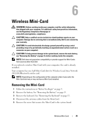
... the system board. NOTE: Depending on page 9. 2 Remove the battery. See "Removing the Keyboard" on your warranty. CAUTION: Only a certified service technician should perform repairs on page 15. 4 Disconnect the antenna cables from sources other than Dell. NOTE: Dell does not guarantee compatibility or provide support for Wireless Local Area Network (WLAN)/Bluetooth combo card. Removing the Mini-Card 1 Follow the instructions in "Before You Begin" on the configuration of...
... the system board. NOTE: Depending on page 9. 2 Remove the battery. See "Removing the Keyboard" on your warranty. CAUTION: Only a certified service technician should perform repairs on page 15. 4 Disconnect the antenna cables from sources other than Dell. NOTE: Dell does not guarantee compatibility or provide support for Wireless Local Area Network (WLAN)/Bluetooth combo card. Removing the Mini-Card 1 Follow the instructions in "Before You Begin" on the configuration of...
Owners Manual
Page 27
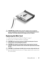
... the safety information that shipped with your computer. Wireless Mini-Card 27 If you use excessive force, you feel resistance, check the connectors on the card and on the system board, and realign the card. CAUTION: The connectors are keyed to slide the card into the connector on page 9. 2 Remove the new Mini-Card from its packaging. If you may damage...
... the safety information that shipped with your computer. Wireless Mini-Card 27 If you use excessive force, you feel resistance, check the connectors on the card and on the system board, and realign the card. CAUTION: The connectors are keyed to slide the card into the connector on page 9. 2 Remove the new Mini-Card from its packaging. If you may damage...
Owners Manual
Page 28
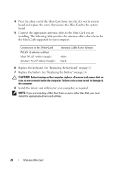
4 Press the other than Dell, you must install the appropriate drivers and utilities. 28 Wireless Mini-Card CAUTION: Before turning on the computer, replace all screws and ensure that secures the Mini-Card to the system board. 5 Connect the appropriate antenna cables to the computer. 8 Install the drivers and utilities for the Mini-Cards supported by your computer, as required. Failure to do so may result in damage...
4 Press the other than Dell, you must install the appropriate drivers and utilities. 28 Wireless Mini-Card CAUTION: Before turning on the computer, replace all screws and ensure that secures the Mini-Card to the system board. 5 Connect the appropriate antenna cables to the computer. 8 Install the drivers and utilities for the Mini-Cards supported by your computer, as required. Failure to do so may result in damage...
Owners Manual
Page 37
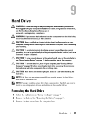
... need to servicing that shipped with your computer. Removing the Hard Drive 1 Follow the instructions in Sleep state. See "Removing the Battery" on page 9. 2 Remove the battery. WARNING: If you remove the hard drive from sources other than Dell. NOTE: Dell does not guarantee compatibility or provide support for hard drives from the computer when the drive is hot, do not touch the metal housing of the hard drive. Damage due to install an operating system, drivers...
... need to servicing that shipped with your computer. Removing the Hard Drive 1 Follow the instructions in Sleep state. See "Removing the Battery" on page 9. 2 Remove the battery. WARNING: If you remove the hard drive from sources other than Dell. NOTE: Dell does not guarantee compatibility or provide support for hard drives from the computer when the drive is hot, do not touch the metal housing of the hard drive. Damage due to install an operating system, drivers...
Owners Manual
Page 39
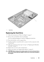
... Assembly" on page 32. 6 Replace the two screws to the computer base. 7 Replace the battery. Hard Drive 39 CAUTION: Before turning on page 14. See "Replacing the Battery" on the computer, replace all screws and ensure that no stray screws remain inside the computer. 1 1 hard drive Replacing the Hard Drive 1 Follow the instructions in "Before You Begin" on page 9. 2 Remove the new hard drive from step 3 to step 7 in...
... Assembly" on page 32. 6 Replace the two screws to the computer base. 7 Replace the battery. Hard Drive 39 CAUTION: Before turning on page 14. See "Replacing the Battery" on the computer, replace all screws and ensure that no stray screws remain inside the computer. 1 1 hard drive Replacing the Hard Drive 1 Follow the instructions in "Before You Begin" on page 9. 2 Remove the new hard drive from step 3 to step 7 in...
Owners Manual
Page 44
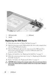
.... 5 Follow the instructions from step 3 to step 7 in "Replacing the Palm-Rest Assembly" on the computer, replace all screws and ensure that no stray screws remain inside the computer. Failure to do so may result in damage to the connector on the USB board. 4 Replace the hard drive. CAUTION: Before turning on page 32. 6 Replace the battery. 1 2 3 1 USB-board cable 3 tabs (2) 2 USB board Replacing the USB Board 1 Follow the...
.... 5 Follow the instructions from step 3 to step 7 in "Replacing the Palm-Rest Assembly" on the computer, replace all screws and ensure that no stray screws remain inside the computer. Failure to do so may result in damage to the connector on the USB board. 4 Replace the hard drive. CAUTION: Before turning on page 32. 6 Replace the battery. 1 2 3 1 USB-board cable 3 tabs (2) 2 USB board Replacing the USB Board 1 Follow the...
Owners Manual
Page 47
... 9. 2 Remove the battery. CAUTION: To help prevent damage to stop. Removing the Processor Module 1 Follow the instructions in "Removing the Palm-Rest Assembly" on your computer). CAUTION: Handle components and cards by your warranty. 13 Processor Module (For Inspiron 15-N5050/15-N5040 Only) WARNING: Before working inside your computer, read the safety information that is not authorized by Dell is not covered by...
... 9. 2 Remove the battery. CAUTION: To help prevent damage to stop. Removing the Processor Module 1 Follow the instructions in "Removing the Palm-Rest Assembly" on your computer). CAUTION: Handle components and cards by your warranty. 13 Processor Module (For Inspiron 15-N5050/15-N5040 Only) WARNING: Before working inside your computer, read the safety information that is not authorized by Dell is not covered by...
Owners Manual
Page 48
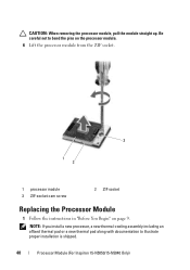
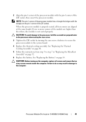
CAUTION: When removing the processor module, pull the module straight up. Be careful not to illustrate proper installation is shipped. 48 Processor Module (For Inspiron 15-N5050/15-N5040 Only) NOTE: If you install a new processor, a new thermal-cooling assembly including an affixed thermal pad or a new thermal pad along with documentation to bend the pins on the processor module. 6 Lift the processor module from the ZIF socket. 3 1 2 1 processor module 3 ZIF-socket cam screw 2 ZIF socket Replacing the Processor Module 1 Follow the instructions in "Before You Begin" on page 9.
CAUTION: When removing the processor module, pull the module straight up. Be careful not to illustrate proper installation is shipped. 48 Processor Module (For Inspiron 15-N5050/15-N5040 Only) NOTE: If you install a new processor, a new thermal-cooling assembly including an affixed thermal pad or a new thermal pad along with documentation to bend the pins on the processor module. 6 Lift the processor module from the ZIF socket. 3 1 2 1 processor module 3 ZIF-socket cam screw 2 ZIF socket Replacing the Processor Module 1 Follow the instructions in "Before You Begin" on page 9.
Owners Manual
Page 49
... socket, then insert the processor module. Processor Module (For Inspiron 15-N5050/15-N5040 Only) 49 Failure to do so may result in "Replacing the Palm-Rest Assembly" on page 32. 6 Replace the battery. See "Replacing the Thermal Cooling Assembly" on page 46. 5 Follow the instructions from step 3 to step 7 in damage to the system board. 4 Replace the thermal cooling assembly. When...
... socket, then insert the processor module. Processor Module (For Inspiron 15-N5050/15-N5040 Only) 49 Failure to do so may result in "Replacing the Palm-Rest Assembly" on page 32. 6 Replace the battery. See "Replacing the Thermal Cooling Assembly" on page 46. 5 Follow the instructions from step 3 to step 7 in damage to the system board. 4 Replace the thermal cooling assembly. When...
Owners Manual
Page 53
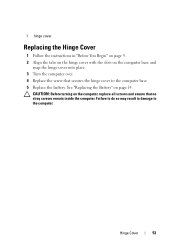
CAUTION: Before turning on the computer, replace all screws and ensure that secures the hinge cover to the computer. Hinge Cover 53 See "Replacing the Battery" on the computer base and snap the hinge cover into place. 3 Turn the computer over. 4 Replace the screw that no stray screws remain inside the computer. Failure to do so may result in "Before You Begin" on page 9. 2 Align the tabs on the hinge cover with the slots on page 14. 1 hinge cover Replacing the Hinge Cover 1 Follow the instructions in damage to the computer base. 5 Replace the battery.
CAUTION: Before turning on the computer, replace all screws and ensure that secures the hinge cover to the computer. Hinge Cover 53 See "Replacing the Battery" on the computer base and snap the hinge cover into place. 3 Turn the computer over. 4 Replace the screw that no stray screws remain inside the computer. Failure to do so may result in "Before You Begin" on page 9. 2 Align the tabs on the hinge cover with the slots on page 14. 1 hinge cover Replacing the Hinge Cover 1 Follow the instructions in damage to the computer base. 5 Replace the battery.
Owners Manual
Page 65
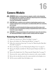
... "Removing the Battery" on page 13. 3 Follow the instructions from the display cover. CAUTION: To help prevent damage to the system board, remove the main battery, see the Regulatory Compliance Homepage at www.dell.com/regulatory_compliance. Removing the Camera Module 1 Follow the instructions in "Removing the Palm-Rest Assembly" on your computer. CAUTION: Only a certified service technician should perform repairs on page 55. 6 Remove the display bezel. See "Removing...
... "Removing the Battery" on page 13. 3 Follow the instructions from the display cover. CAUTION: To help prevent damage to the system board, remove the main battery, see the Regulatory Compliance Homepage at www.dell.com/regulatory_compliance. Removing the Camera Module 1 Follow the instructions in "Removing the Palm-Rest Assembly" on your computer. CAUTION: Only a certified service technician should perform repairs on page 55. 6 Remove the display bezel. See "Removing...
Owners Manual
Page 67
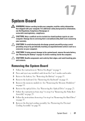
... -1 media card reader. 3 Remove the battery. System Board 67 For additional safety best practices information, see "Removing the Battery" on page 29. 8 Follow the instructions from the 3-in "Removing the Hard Drive" on your computer. See "Removing the Thermal Cooling Assembly" on page 13. 4 Remove the keyboard. 17 System Board WARNING: Before working inside your computer, read the safety information that is not authorized by Dell is not covered...
... -1 media card reader. 3 Remove the battery. System Board 67 For additional safety best practices information, see "Removing the Battery" on page 29. 8 Follow the instructions from the 3-in "Removing the Hard Drive" on your computer. See "Removing the Thermal Cooling Assembly" on page 13. 4 Remove the keyboard. 17 System Board WARNING: Before working inside your computer, read the safety information that is not authorized by Dell is not covered...
Owners Manual
Page 70
... Replace the battery. See "Replacing the Keyboard" on page 14. 14 Replace any removed cards or blanks in the 3-in-1 media card reader. 9 Follow the instructions from step 3 to the security tab and enter the service tag in the Set Service Tag field. 70 System Board See "Entering the Service Tag in the BIOS" on page 32. 10 Replace the optical drive. Entering the Service Tag in the BIOS 1 Ensure that the AC adapter is...
... Replace the battery. See "Replacing the Keyboard" on page 14. 14 Replace any removed cards or blanks in the 3-in-1 media card reader. 9 Follow the instructions from step 3 to the security tab and enter the service tag in the Set Service Tag field. 70 System Board See "Entering the Service Tag in the BIOS" on page 32. 10 Replace the optical drive. Entering the Service Tag in the BIOS 1 Ensure that the AC adapter is...


