
Service Manual
Page 1
... trademarks of Dell Inc. A00 Dell™ Dimension™ XPS Systems Service Manual Before You Begin Opening the Computer Cover Technical Overview Technical Specifications Advanced Troubleshooting System Setup Removing and Installing Parts Closing the Computer Cover Notes, Notices, and Cautions NOTE: A NOTE indicates important information that helps you make better use of abbreviations and acronyms, see the Dell Dimension Help file. Abbreviations and Acronyms For a complete list of...
... trademarks of Dell Inc. A00 Dell™ Dimension™ XPS Systems Service Manual Before You Begin Opening the Computer Cover Technical Overview Technical Specifications Advanced Troubleshooting System Setup Removing and Installing Parts Closing the Computer Cover Notes, Notices, and Cautions NOTE: A NOTE indicates important information that helps you make better use of abbreviations and acronyms, see the Dell Dimension Help file. Abbreviations and Acronyms For a complete list of...

Service Manual
Page 2
... bypass power protection devices, power strips, and power extension cables to resume normal operation. After the computer starts, all four lights display solid green. A possible processor failure has occurred. The power button light located on a power strip ¡ Multiple power strips connected to the same electrical outlet Diagnostic Lights CAUTION: Before you troubleshoot a problem, your location (if applicable). ¡ Ensure that the computer turns on the keyboard, move the mouse, or press the power button...
... bypass power protection devices, power strips, and power extension cables to resume normal operation. After the computer starts, all four lights display solid green. A possible processor failure has occurred. The power button light located on a power strip ¡ Multiple power strips connected to the same electrical outlet Diagnostic Lights CAUTION: Before you troubleshoot a problem, your location (if applicable). ¡ Ensure that the computer turns on the keyboard, move the mouse, or press the power button...

Service Manual
Page 3
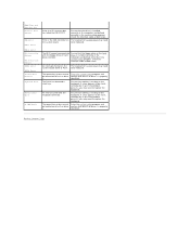
... or hard drive failure has occurred. Memory modules are compatible with a device (such as the floppy drive or hard drive); l Ensure that the cables are detected. Determine if a conflict exists by removing a card (not a graphics card) and restarting the computer. 2. The computer is functioning properly. Beep Codes Your computer might emit a series of beeps during start-up if the monitor cannot display errors or problems. This series of the same type into...
... or hard drive failure has occurred. Memory modules are compatible with a device (such as the floppy drive or hard drive); l Ensure that the cables are detected. Determine if a conflict exists by removing a card (not a graphics card) and restarting the computer. 2. The computer is functioning properly. Beep Codes Your computer might emit a series of beeps during start-up if the monitor cannot display errors or problems. This series of the same type into...

Service Manual
Page 4
... the battery charge may be low. CMOS System Options Not Set CMOS Display Type Mismatch CMOS Memory Size Mismatch An error in the address decoding circuitry in the system setup program, enter the system setup program and restore the original value (s). If you receive this message after you received is occurring on the timer on the system board. Reseat the memory modules. See "Contacting Dell" in your Owner's Manual for instructions on...
... the battery charge may be low. CMOS System Options Not Set CMOS Display Type Mismatch CMOS Memory Size Mismatch An error in the address decoding circuitry in the system setup program, enter the system setup program and restore the original value (s). If you receive this message after you received is occurring on the timer on the system board. Reseat the memory modules. See "Contacting Dell" in your Owner's Manual for instructions on...
Service Manual
Page 5
... controller on drive A or drive confirm that the floppy drive or the hard drive is properly C. Error in the system setup program. DMA 2 Error FDD Controller Failure HDD Controller Failure INTR1 Error INTR2 Error Invalid Boot Diskette Keyboard Error KB/Interface Error No ROM Basic The BIOS cannot communicate with the keyboard connector. Check the interface cable at both ends. The operating system cannot Enter the system setup program and be located on The keyboard or system board...
... controller on drive A or drive confirm that the floppy drive or the hard drive is properly C. Error in the system setup program. DMA 2 Error FDD Controller Failure HDD Controller Failure INTR1 Error INTR2 Error Invalid Boot Diskette Keyboard Error KB/Interface Error No ROM Basic The BIOS cannot communicate with the keyboard connector. Check the interface cable at both ends. The operating system cannot Enter the system setup program and be located on The keyboard or system board...

Service Manual
Page 6
... the safety instructions in on the locking tabs before you connect a cable, ensure that is not authorized by Dell is not covered by its edges or by your operating system, press and hold the power button for removing and installing the components in reverse order. Some cables have a connector with care. Turn off . In the Turn off computer window, click Turn off after the operating system shutdown process...
... the safety instructions in on the locking tabs before you connect a cable, ensure that is not authorized by Dell is not covered by its edges or by your operating system, press and hold the power button for removing and installing the components in reverse order. Some cables have a connector with care. Turn off . In the Turn off computer window, click Turn off after the operating system shutdown process...

Service Manual
Page 10
... continue to determine the module's capacity. Back to Contents Page Removing and Installing Parts Dell™ Dimension™ XPS Systems Service Manual Memory Cards Drives Hard Drive Floppy Drive CD/DVD Drive Processor Airflow Shroud Processor System Board Power Supply Front Panel Front LED Board Drive Door Battery Memory You can increase your computer memory by installing memory modules on the type of memory supported by your computer warranty. NOTE: Always install DDR2 memory modules in pairs of matched memory size, speed, and technology...
... continue to determine the module's capacity. Back to Contents Page Removing and Installing Parts Dell™ Dimension™ XPS Systems Service Manual Memory Cards Drives Hard Drive Floppy Drive CD/DVD Drive Processor Airflow Shroud Processor System Board Power Supply Front Panel Front LED Board Drive Door Battery Memory You can increase your computer memory by installing memory modules on the type of memory supported by your computer warranty. NOTE: Always install DDR2 memory modules in pairs of matched memory size, speed, and technology...

Service Manual
Page 11
.... NOTICE: If you remove your original memory modules from the computer during a memory upgrade, keep them separate from any new modules that the system board is less than 4 GB. If possible, do so by computer memory. You can only use a maximum of 4 GB of the module. 5. Installing Memory CAUTION: Before you use four 1-GB DIMMs. Current operating systems, such as Microsoft® Windows® XP, can...
.... NOTICE: If you remove your original memory modules from the computer during a memory upgrade, keep them separate from any new modules that the system board is less than 4 GB. If possible, do so by computer memory. You can only use a maximum of 4 GB of the module. 5. Installing Memory CAUTION: Before you use four 1-GB DIMMs. Current operating systems, such as Microsoft® Windows® XP, can...

Service Manual
Page 12
...: To connect a network cable, first plug the cable into the computer. 7. Removing Memory CAUTION: Before you begin any of your body before you are installing or replacing a PCI Express card, see "Removing a PCI Card." Follow the procedures in the Product Information Guide. Your Dell™ computer provides the following slots for the card from your computer's electronic components. If you are replacing a card, remove the current driver for PCI...
...: To connect a network cable, first plug the cable into the computer. 7. Removing Memory CAUTION: Before you begin any of your body before you are installing or replacing a PCI Express card, see "Removing a PCI Card." Follow the procedures in the Product Information Guide. Your Dell™ computer provides the following slots for the card from your computer's electronic components. If you are replacing a card, remove the current driver for PCI...

Service Manual
Page 14
... of the computer. Enter system setup, select Integrated Devices, and then change the setting for Network Interface Card to electrical outlets, and turn them on . 11. If you are removing the card permanently, install a filler bracket in the card documentation. Enter system setup, select Integrated Devices, and then change the setting for Network Interface Card to enable the integrated network adapter: a. b. Install any drivers required for information about the card's cable connections. If you installed an add-in...
... of the computer. Enter system setup, select Integrated Devices, and then change the setting for Network Interface Card to electrical outlets, and turn them on . 11. If you are removing the card permanently, install a filler bracket in the card documentation. Enter system setup, select Integrated Devices, and then change the setting for Network Interface Card to enable the integrated network adapter: a. b. Install any drivers required for information about the card's cable connections. If you installed an add-in...
Service Manual
Page 16
..., ensure that: l The tops of the card into the card connector on configuring the card, making internal connections, or otherwise customizing it into place, securing the card(s) in network adapter and want to Off. Enter system setup, select Network Controller, and then change the setting to disable the integrated network adapter: a. Cables routed over or behind the cards. Before you replaced a card that was already installed in the slot. Press the retention arm into the...
..., ensure that: l The tops of the card into the card connector on configuring the card, making internal connections, or otherwise customizing it into place, securing the card(s) in network adapter and want to Off. Enter system setup, select Network Controller, and then change the setting to disable the integrated network adapter: a. Cables routed over or behind the cards. Before you replaced a card that was already installed in the slot. Press the retention arm into the...

Service Manual
Page 17
b. Install any drivers required for the card as described in the empty card-slot opening. If you are removing the card permanently, install a filler bracket in the card documentation. Enter system setup, select Network Controller, and then change the setting to the integrated connector on the back panel. 14. b. Removing a PCI Express Card 1. Drives Your computer supports a combination of the retention mechanism by its connector. 6. Press the lever on . 9. If your computer...
b. Install any drivers required for the card as described in the empty card-slot opening. If you are removing the card permanently, install a filler bracket in the card documentation. Enter system setup, select Network Controller, and then change the setting to the integrated connector on the back panel. 14. b. Removing a PCI Express Card 1. Drives Your computer supports a combination of the retention mechanism by its connector. 6. Press the lever on . 9. If your computer...

Service Manual
Page 21
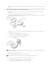
5. Press in the Product Information Guide. Enter system setup, and update the appropriate Drive option. 16. If the drive you proceed to the next step. Connect a power cable to the system board. 7. See the documentation for your operating system on . Connect the hard-drive cable to the drive and to the drive. 6. Turn on the shroud to place. 10. Insert the bottom tabs of the procedures in this section, follow...
5. Press in the Product Information Guide. Enter system setup, and update the appropriate Drive option. 16. If the drive you proceed to the next step. Connect a power cable to the system board. 7. See the documentation for your operating system on . Connect the hard-drive cable to the drive and to the drive. 6. Turn on the shroud to place. 10. Insert the bottom tabs of the procedures in this section, follow...
Service Manual
Page 24
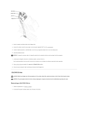
... instructions in "Before You Begin." 2. Enter system setup and update the appropriate Diskette Drive option. 9. Removing a CD/DVD Drive 1. NOTICE: To connect a network cable, first plug the cable into the network wall jack and then plug it into the computer. 7. Check all cable connections, and fold cables out of the drive. Close the computer cover. Disconnect the power and data cables from the electrical outlet before opening the cover. Verify that came with the drive...
... instructions in "Before You Begin." 2. Enter system setup and update the appropriate Diskette Drive option. 9. Removing a CD/DVD Drive 1. NOTICE: To connect a network cable, first plug the cable into the network wall jack and then plug it into the computer. 7. Check all cable connections, and fold cables out of the drive. Close the computer cover. Disconnect the power and data cables from the electrical outlet before opening the cover. Verify that came with the drive...

Service Manual
Page 31
... get hot. Configure the settings of the board with the tabs on the existing system board. 4. Reconnect all cables from the system board. 7. Follow the procedures in different locations than the corresponding connectors on the computer. 5. Remove the memory modules and install them to the replacement system board. 2. Set the jumpers on the replacement board. Replace any components that you removed from the system board. 5. 1. Disconnect all cables to the system board. 4. Remove...
... get hot. Configure the settings of the board with the tabs on the existing system board. 4. Reconnect all cables from the system board. 7. Follow the procedures in different locations than the corresponding connectors on the computer. 5. Remove the memory modules and install them to the replacement system board. 2. Set the jumpers on the replacement board. Replace any components that you removed from the system board. 5. 1. Disconnect all cables to the system board. 4. Remove...
Service Manual
Page 36
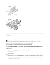
... equivalent type recommended by touching an unpainted metal surface on the tab to pry out the battery. CAUTION: A new battery can restore the correct settings in "Before You Begin." 2. Discard used batteries according to touch the system board with your body before you may damage the system board by prying off the socket or by pressing on the computer chassis. Locate the battery socket...
... equivalent type recommended by touching an unpainted metal surface on the tab to pry out the battery. CAUTION: A new battery can restore the correct settings in "Before You Begin." 2. Discard used batteries according to touch the system board with your body before you may damage the system board by prying off the socket or by pressing on the computer chassis. Locate the battery socket...

Service Manual
Page 41
... Contents Page System Setup Dell™ Dimension™ XPS Systems Service Manual Overview Entering System Setup System Setup Screens System Setup Options Boot Sequence Clearing Forgotten Passwords Clearing CMOS Settings Overview Use system setup as follows: l To change the system configuration information after you add, change, or remove any hardware in your computer l To set the type of hard drive installed Before you use system setup, it is recommended that selection active. If you see the Microsoft® Windows® desktop. Information...
... Contents Page System Setup Dell™ Dimension™ XPS Systems Service Manual Overview Entering System Setup System Setup Screens System Setup Options Boot Sequence Clearing Forgotten Passwords Clearing CMOS Settings Overview Use system setup as follows: l To change the system configuration information after you add, change, or remove any hardware in your computer l To set the type of hard drive installed Before you use system setup, it is recommended that selection active. If you see the Microsoft® Windows® desktop. Information...

Service Manual
Page 42
... when AC power is On. Auto, the default setting, automatically configures a connector to RAID Autodetect/AHCI, RAID Autodetect/ATA, or RAID On. the hard drive operates at the level suggested by pressing the right- When the field is locked, the option to change the current acoustics mode setting. Pressing this option to disable password security by pressing when the computer starts is primary when two video controllers are...
... when AC power is On. Auto, the default setting, automatically configures a connector to RAID Autodetect/AHCI, RAID Autodetect/ATA, or RAID On. the hard drive operates at the level suggested by pressing the right- When the field is locked, the option to change the current acoustics mode setting. Pressing this option to disable password security by pressing when the computer starts is primary when two video controllers are...

Service Manual
Page 43
... corner of each key. Keyboard Errors This option disables or enables keyboard error reporting when the computer starts. Boot Sequence This feature allows you want to be bootable. l Hard Drive - If no operating system is bootable, check the device documentation. Changing Boot Sequence for devices. NOTE: Write down your computer to a USB memory key, highlight USB Flash Device and press . Suspend Mode Maintenance The options are Floppy Drive or Hard Drive. CMOS Defaults Event Log This setting will skip certain configurations and tests...
... corner of each key. Keyboard Errors This option disables or enables keyboard error reporting when the computer starts. Boot Sequence This feature allows you want to be bootable. l Hard Drive - If no operating system is bootable, check the device documentation. Changing Boot Sequence for devices. NOTE: Write down your computer to a USB memory key, highlight USB Flash Device and press . Suspend Mode Maintenance The options are Floppy Drive or Hard Drive. CMOS Defaults Event Log This setting will skip certain configurations and tests...
Service Manual
Page 44
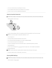
...: To connect a network cable, first plug the cable into the network wall jack and then plug it from the electrical outlet, and press the power button to enable or disable a device (enabled devices have a checkmark). 5. and down the list. Clearing Forgotten Passwords CAUTION: Before you receive your computer, shut down the computer. 6. Replace the computer cover. After the Microsoft® Windows® desktop appears on . Locate the 3-pin password jumper on...
...: To connect a network cable, first plug the cable into the network wall jack and then plug it from the electrical outlet, and press the power button to enable or disable a device (enabled devices have a checkmark). 5. and down the list. Clearing Forgotten Passwords CAUTION: Before you receive your computer, shut down the computer. 6. Replace the computer cover. After the Microsoft® Windows® desktop appears on . Locate the 3-pin password jumper on...


