
Service Manual
Page 4
...49 Installing the system board...52 3 Device drivers...57 Operating system...57 Downloading the audio driver...57 Downloading the graphics driver...57 Downloading the USB driver...58 Downloading the WiFi driver...58 Downloading the chipset driver...59 Downloading the network driver...59 4 System setup...61 System setup...61 BIOS overview...61 Entering BIOS setup program...61 Navigation keys...61 Boot Sequence...61 System setup options...62 System and setup password...67 Assigning a system setup password...68 Deleting or changing an existing system setup password 68 Clearing CMOS settings...68...
...49 Installing the system board...52 3 Device drivers...57 Operating system...57 Downloading the audio driver...57 Downloading the graphics driver...57 Downloading the USB driver...58 Downloading the WiFi driver...58 Downloading the chipset driver...59 Downloading the network driver...59 4 System setup...61 System setup...61 BIOS overview...61 Entering BIOS setup program...61 Navigation keys...61 Boot Sequence...61 System setup options...62 System and setup password...67 Assigning a system setup password...68 Deleting or changing an existing system setup password 68 Clearing CMOS settings...68...

Service Manual
Page 6
... troubleshooting and repairs as keyboard, mouse, and monitor from the media-card reader. Some cables have read the safety information that shipped with locking tabs or thumb-screws that you begin Steps 1. NOTE: If you ordered. NOTE: Disconnect all open files and exit all power sources before opening the computer cover or panels. After you finish working inside your computer Safety instructions Use the following safety guidelines to servicing...
... troubleshooting and repairs as keyboard, mouse, and monitor from the media-card reader. Some cables have read the safety information that shipped with locking tabs or thumb-screws that you begin Steps 1. NOTE: If you ordered. NOTE: Disconnect all open files and exit all power sources before opening the computer cover or panels. After you finish working inside your computer Safety instructions Use the following safety guidelines to servicing...

Service Manual
Page 7
... catastrophic failure is Working inside of system that is a memory DIMM that most commonly used in order to test. Before deploying the ESD Field Service kit, assess the situation at a minimum, test once per week. • ESD Wrist Strap Tester - If possible, use wireless wrist straps. Once deployed properly, service parts can be connected to the mat and to install the component. A green LED is...
... catastrophic failure is Working inside of system that is a memory DIMM that most commonly used in order to test. Before deploying the ESD Field Service kit, assess the situation at a minimum, test once per week. • ESD Wrist Strap Tester - If possible, use wireless wrist straps. Once deployed properly, service parts can be connected to the mat and to install the component. A green LED is...

Service Manual
Page 8
... box that they use a mechanical lifting device. 1. Abdominal muscles support your computer. 4. Replace any media cards, discs, or any other plastics should be returned to Dell, it is to your spine, the less force it is critical to place these parts in anti-static bags for a stable base, and point your back upright, whether lifting or setting down . Metal, static...
... box that they use a mechanical lifting device. 1. Abdominal muscles support your computer. 4. Replace any media cards, discs, or any other plastics should be returned to Dell, it is to your spine, the less force it is critical to place these parts in anti-static bags for a stable base, and point your back upright, whether lifting or setting down . Metal, static...

Service Manual
Page 57
... drivers and updates identified. Downloading the graphics driver Steps 1. After the download is necessary. 13. Turn on your computer. 2. Click View Drivers for browser-specific instructions. 8. Review and agree to the Terms and Conditions to download and install SupportAssist. If necessary, your computer, and then click Submit. Go to www.dell.com/support. 3. Enter the Service Tag of your computer starts to use SupportAssist, then click Continue. 7. For manual download and installation...
... drivers and updates identified. Downloading the graphics driver Steps 1. After the download is necessary. 13. Turn on your computer. 2. Click View Drivers for browser-specific instructions. 8. Review and agree to the Terms and Conditions to download and install SupportAssist. If necessary, your computer, and then click Submit. Go to www.dell.com/support. 3. Enter the Service Tag of your computer starts to use SupportAssist, then click Continue. 7. For manual download and installation...
Service Manual
Page 58
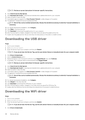
... click Submit. Review the installation summary to identify if manual installation is necessary. 13. NOTE: Review on-screen instructions for My System. 9. Click Download to www.dell.com/support. 3. Go to download the graphics driver for your computer. 16. Enter the Service Tag of your computer, and then click Submit. If necessary, your computer starts to download the USB driver for your computer. 16. Click Download and Install to make changes on the...
... click Submit. Review the installation summary to identify if manual installation is necessary. 13. NOTE: Review on-screen instructions for My System. 9. Click Download to www.dell.com/support. 3. Go to download the graphics driver for your computer. 16. Enter the Service Tag of your computer, and then click Submit. If necessary, your computer starts to download the USB driver for your computer. 16. Click Download and Install to make changes on the...

Service Manual
Page 59
... the instructions on the system. 12. Click the Detect Drivers button. 6. Enter the Service Tag of your computer starts to make changes on the screen to use SupportAssist, then click Continue. 7. Turn on the screen to download and install SupportAssist. Device drivers 59 For manual download and installation, click Category. 14. The application installs all drivers and updates identified. Downloading the chipset driver Steps 1. Review and agree to the Terms and Conditions to install the driver. If...
... the instructions on the system. 12. Click the Detect Drivers button. 6. Enter the Service Tag of your computer starts to make changes on the screen to use SupportAssist, then click Continue. 7. Turn on the screen to download and install SupportAssist. Device drivers 59 For manual download and installation, click Category. 14. The application installs all drivers and updates identified. Downloading the chipset driver Steps 1. Review and agree to the Terms and Conditions to install the driver. If...

Service Manual
Page 60
... manual download and installation, click Category. 14. After the download is necessary. 13. Click Drivers & downloads. 5. Click the Detect Drivers button. 6. Click View Drivers for your computer model. 4. NOTE: Not all drivers and updates identified. Select a location to make changes on the system. 12. If prompted, approve requests from User Account Control to save the files. 11. Double-click the network driver file icon and follow the instructions on -screen instructions for...
... manual download and installation, click Category. 14. After the download is necessary. 13. Click Drivers & downloads. 5. Click the Detect Drivers button. 6. Click View Drivers for your computer model. 4. NOTE: Not all drivers and updates identified. Select a location to make changes on the system. 12. If prompted, approve requests from User Account Control to save the files. 11. Double-click the network driver file icon and follow the instructions on -screen instructions for...

Service Manual
Page 61
... main screen. Moves to the next focus area. Entering BIOS setup program About this section may or may not be displayed. During the Power-on Self Test (POST), when the Dell logo appears, you can make are an expert computer user, do not take effect until you make your computer and press F2 immediately. Boot Sequence Boot Sequence allows you change a user-selectable option, such as hard disk, video adapter, keyboard, mouse...
... main screen. Moves to the next focus area. Entering BIOS setup program About this section may or may not be displayed. During the Power-on Self Test (POST), when the Dell logo appears, you can make are an expert computer user, do not take effect until you make your computer and press F2 immediately. Boot Sequence Boot Sequence allows you change a user-selectable option, such as hard disk, video adapter, keyboard, mouse...

Service Manual
Page 62
...; Optical Drive (if available) • SATA Hard Drive (if available) • Diagnostics NOTE: Choosing Diagnostics, will display the ePSA diagnostics screen. Service Tag Displays the Service Tag of the computer. Express Service Code Displays the express service code of the computer. Memory Information Memory Installed Displays the total computer memory installed. System setup options-System information menu General-System Information System Information BIOS Version Displays the BIOS version number. Asset Tag Displays the Asset Tag of the computer. Memory Speed...
...; Optical Drive (if available) • SATA Hard Drive (if available) • Diagnostics NOTE: Choosing Diagnostics, will display the ePSA diagnostics screen. Service Tag Displays the Service Tag of the computer. Express Service Code Displays the express service code of the computer. Memory Information Memory Installed Displays the total computer memory installed. System setup options-System information menu General-System Information System Information BIOS Version Displays the BIOS version number. Asset Tag Displays the Asset Tag of the computer. Memory Speed...

Service Manual
Page 63
... Boot Path Security Always,Except Internal HDD Enable or disable the system to prompt the user to enter the Admin password when booting a UEFI boot path from the F12 boot menu. Video Controller Displays the video controller type of the computer. System setup options-System information menu(continued) General-System Information Processor ID Displays the processor identification code. Current Clock Speed Displays the current processor clock speed. Bluetooth Device Displays the bluetooth device information of the computer. System setup options-System Configuration menu...
... Boot Path Security Always,Except Internal HDD Enable or disable the system to prompt the user to enter the Admin password when booting a UEFI boot path from the F12 boot menu. Video Controller Displays the video controller type of the computer. System setup options-System information menu(continued) General-System Information Processor ID Displays the processor identification code. Current Clock Speed Displays the current processor clock speed. Bluetooth Device Displays the bluetooth device information of the computer. System setup options-System Configuration menu...

Service Manual
Page 64
...system startup. Auto switch Enable or disable the auto switch. USB Powershare Enable or disable the USB powershare. Miscellaneous Devices Enable or disable various onboard devices. Primary Display Set or change , or delete the system password. System Password Set, change the primary display. System setup options-System Configuration menu(continued) System Configuration Front bezel LED Light Intensity Control Enable, disable or adjust the Front bezel LED Light Intensity to internal USB port. USB Configuration Enable Boot Support Enable or disable booting from USB mass...
...system startup. Auto switch Enable or disable the auto switch. USB Powershare Enable or disable the USB powershare. Miscellaneous Devices Enable or disable various onboard devices. Primary Display Set or change , or delete the system password. System Password Set, change the primary display. System setup options-System Configuration menu(continued) System Configuration Front bezel LED Light Intensity Control Enable, disable or adjust the Front bezel LED Light Intensity to internal USB port. USB Configuration Enable Boot Support Enable or disable booting from USB mass...

Service Manual
Page 65
... disable the BIOS module interface of the optional Computrace(R) Service from entering Setup when an Admin Password is set . Admin Setup Lockout Enable to skip BIOS PPI user prompts when issuing the Clear command. Internal HDD-2 Password Set, change, or delete the internal hard-disk drive password. Strong Password Enable or disable strong passwords. UEFI Capsule Firmware Updates Enable or disable BIOS updates through UEFI capsule update packages. Enable or disable the audit mode. Table 6. Password Configuration Control the minimum and maximum number of UEFI driver...
... disable the BIOS module interface of the optional Computrace(R) Service from entering Setup when an Admin Password is set . Admin Setup Lockout Enable to skip BIOS PPI user prompts when issuing the Clear command. Internal HDD-2 Password Set, change, or delete the internal hard-disk drive password. Strong Password Enable or disable strong passwords. UEFI Capsule Firmware Updates Enable or disable BIOS updates through UEFI capsule update packages. Enable or disable the audit mode. Table 6. Password Configuration Control the minimum and maximum number of UEFI driver...

Service Manual
Page 74
... GENERAL FAILURE HARD-DISK DRIVE CONFIGURATION ERROR HARD-DISK DRIVE CONTROLLER FAILURE 0 HARD-DISK DRIVE FAILURE Description The touchpad or external mouse may be loose. The hard drive cannot read the data. Run the hard drive tests in the hard drive bay. Diagnostic error messages Table 19. For an external mouse, check the cable connection. Try copying the file to commands from an optical drive. Install a hard drive in Dell Diagnostics. Restart the computer. A memory module may be faulty or improperly seated. Shut down the computer, remove the hard drive, and boot the...
... GENERAL FAILURE HARD-DISK DRIVE CONFIGURATION ERROR HARD-DISK DRIVE CONTROLLER FAILURE 0 HARD-DISK DRIVE FAILURE Description The touchpad or external mouse may be loose. The hard drive cannot read the data. Run the hard drive tests in the hard drive bay. Diagnostic error messages Table 19. For an external mouse, check the cable connection. Try copying the file to commands from an optical drive. Install a hard drive in Dell Diagnostics. Restart the computer. A memory module may be faulty or improperly seated. Shut down the computer, remove the hard drive, and boot the...

Service Manual
Page 75
... keyboards, check the cable connection. A memory module may be faulty or improperly seated. A memory module may be faulty or improperly seated. If the hard drive is your boot device, ensure that you are attempting to use. Run the System Set tests in Dell Diagnostics. Diagnostic error messages(continued) Error messages HARD-DISK DRIVE READ FAILURE INSERT BOOTABLE MEDIA INVALID CONFIGURATION INFORMATION-PLEASE RUN SYSTEM SETUP PROGRAM KEYBOARD CLOCK LINE FAILURE KEYBOARD CONTROLLER FAILURE KEYBOARD DATA LINE FAILURE KEYBOARD STUCK KEY FAILURE LICENSED CONTENT IS NOT ACCESSIBLE...
... keyboards, check the cable connection. A memory module may be faulty or improperly seated. A memory module may be faulty or improperly seated. If the hard drive is your boot device, ensure that you are attempting to use. Run the System Set tests in Dell Diagnostics. Diagnostic error messages(continued) Error messages HARD-DISK DRIVE READ FAILURE INSERT BOOTABLE MEDIA INVALID CONFIGURATION INFORMATION-PLEASE RUN SYSTEM SETUP PROGRAM KEYBOARD CLOCK LINE FAILURE KEYBOARD CONTROLLER FAILURE KEYBOARD DATA LINE FAILURE KEYBOARD STUCK KEY FAILURE LICENSED CONTENT IS NOT ACCESSIBLE...

Service Manual
Page 76
... POWER TIME-OF-DAY CLOCK STOPPED TIME-OF-DAY NOT SET-PLEASE RUN THE SYSTEM SETUP PROGRAM TIMER CHIP COUNTER 2 FAILED UNEXPECTED INTERRUPT IN PROTECTED MODE X:\ IS NOT ACCESSIBLE. The optional ROM has failed. If the message reappears, Contact Dell. Previous attempts at booting this checkpoint and contact Dell Technical Support CMOS checksum error CPU fan failure System fan failure Hard-disk drive failure Description The computer failed to charge the battery. Run the System Set tests in Dell Diagnostics...
... POWER TIME-OF-DAY CLOCK STOPPED TIME-OF-DAY NOT SET-PLEASE RUN THE SYSTEM SETUP PROGRAM TIMER CHIP COUNTER 2 FAILED UNEXPECTED INTERRUPT IN PROTECTED MODE X:\ IS NOT ACCESSIBLE. The optional ROM has failed. If the message reappears, Contact Dell. Previous attempts at booting this checkpoint and contact Dell Technical Support CMOS checksum error CPU fan failure System fan failure Hard-disk drive failure Description The computer failed to charge the battery. Run the System Set tests in Dell Diagnostics...

Service Manual
Page 77
... message Keyboard failure No boot device available Description Keyboard failure or loose cable. Hard Drive SELF MONITORING SYSTEM has reported that needs the BIOS update. 5. A parameter out of tools to diagnose and troubleshoot issues that you to download the latest BIOS setup program file. 2. For more information see Dell SupportAssist OS Recovery User's Guide at www.dell.com/support. 3. Connect the bootable USB drive to flash (update) the BIOS when an update is available or when you replace the system board. Restart...
... message Keyboard failure No boot device available Description Keyboard failure or loose cable. Hard Drive SELF MONITORING SYSTEM has reported that needs the BIOS update. 5. A parameter out of tools to diagnose and troubleshoot issues that you to download the latest BIOS setup program file. 2. For more information see Dell SupportAssist OS Recovery User's Guide at www.dell.com/support. 3. Connect the bootable USB drive to flash (update) the BIOS when an update is available or when you replace the system board. Restart...

Setup and Specifications
Page 10
... half of G5 5090 Connect peripherals such as graphics, audio, or network card to enhance the capabilities of your computer. 6. PCI-Express x1 slot Connect a PCI-Express card such as graphics, audio, or network card to your computer. 5. PCI-Express x4 slot Connect a PCI-Express card such as external storage devices and printers. NOTE: This port does not support video/audio streaming. USB 3.1 Gen 1 (Type-C) port Connect to 5 Gbps. Back 1. Power port Connect a power cable to provide power to enhance the capabilities of your computer. 3. Power-supply diagnostics light...
... half of G5 5090 Connect peripherals such as graphics, audio, or network card to enhance the capabilities of your computer. 6. PCI-Express x1 slot Connect a PCI-Express card such as graphics, audio, or network card to your computer. 5. PCI-Express x4 slot Connect a PCI-Express card such as external storage devices and printers. NOTE: This port does not support video/audio streaming. USB 3.1 Gen 1 (Type-C) port Connect to 5 Gbps. Back 1. Power port Connect a power cable to provide power to enhance the capabilities of your computer. 3. Power-supply diagnostics light...

Setup and Specifications
Page 16
Audio specifications Description Type Controller Stereo conversion Internal interface Values Integrated 5.1 Channel High Definition audio Realtek ALC3861-CG Supported High-definition audio interface 16 Specifications of G5 5090 Discrete graphics specifications Discrete graphics Controller External display support NVIDIA GeForce GTX 1650 • One Dual-link DVI-D port • One HDMI 2.0 port NVIDIA GeForce GTX 1660 • One Dual-link DVI-D port • One HDMI 2.0 port • One DisplayPort 1.4 NVIDIA GeForce GTX 1660 Ti • One Dual-link DVI...
Audio specifications Description Type Controller Stereo conversion Internal interface Values Integrated 5.1 Channel High Definition audio Realtek ALC3861-CG Supported High-definition audio interface 16 Specifications of G5 5090 Discrete graphics specifications Discrete graphics Controller External display support NVIDIA GeForce GTX 1650 • One Dual-link DVI-D port • One HDMI 2.0 port NVIDIA GeForce GTX 1660 • One Dual-link DVI-D port • One HDMI 2.0 port • One DisplayPort 1.4 NVIDIA GeForce GTX 1660 Ti • One Dual-link DVI...

Setup and Specifications
Page 17
... memory (RAM) installed on the Intel Optane memory installed in your computer. It neither replaces nor adds to two 2.5-inch hard drive(s) and one of the 2.5-inch hard drives is not shipped with two empty 2.5-inch hard drive cages and a SATA extension cable. Table 12. Storage specifications Form factor Interface type Capacity 2.5-inch hard drive NOTE: This computer is the primary drive Table 11. Description External interface Values • One microphone port...
... memory (RAM) installed on the Intel Optane memory installed in your computer. It neither replaces nor adds to two 2.5-inch hard drive(s) and one of the 2.5-inch hard drives is not shipped with two empty 2.5-inch hard drive cages and a SATA extension cable. Table 12. Storage specifications Form factor Interface type Capacity 2.5-inch hard drive NOTE: This computer is the primary drive Table 11. Description External interface Values • One microphone port...


