
Owner's Manual
Page 5
Removing The Optical Drive In Cabled Hard-Drive Systems 58 Installing The Optical Drive In Cabled Hard-Drive Systems 59 Cooling Fans...60 Removing A Cooling Fan...60 Installing A Cooling Fan...61 Internal USB Memory Key (Optional)...62 Replacing The Internal USB Key...62 Expansion Cards And Expansion-Card Risers...62 Expansion Card Installation Guidelines...63 Removing An Expansion Card...63 Installing An Expansion Card...65 Removing Expansion-Card Risers 1 And 2...66 Installing Expansion-Card Risers 1 And 2...67 iDRAC Ports Card (Optional)...67 Removing The iDRAC Ports Card...68 Installing ...
Removing The Optical Drive In Cabled Hard-Drive Systems 58 Installing The Optical Drive In Cabled Hard-Drive Systems 59 Cooling Fans...60 Removing A Cooling Fan...60 Installing A Cooling Fan...61 Internal USB Memory Key (Optional)...62 Replacing The Internal USB Key...62 Expansion Cards And Expansion-Card Risers...62 Expansion Card Installation Guidelines...63 Removing An Expansion Card...63 Installing An Expansion Card...65 Removing Expansion-Card Risers 1 And 2...66 Installing Expansion-Card Risers 1 And 2...67 iDRAC Ports Card (Optional)...67 Removing The iDRAC Ports Card...68 Installing ...
Owner's Manual
Page 6
... System Startup Failure...101 Troubleshooting External Connections...101 Troubleshooting The Video Subsystem...101 Troubleshooting A USB Device...101 Troubleshooting A Serial I/O Device...102 Troubleshooting A NIC...102 Troubleshooting A Wet System...102 Troubleshooting A Damaged System...103 Troubleshooting The System Battery...104 Troubleshooting Power Supplies...104 Troubleshooting Cooling Problems...104 Troubleshooting Cooling Fans...105 Troubleshooting System Memory...105 Troubleshooting An Internal USB Key...106 Troubleshooting An SD Card...106 Troubleshooting An Optical Drive...107...
... System Startup Failure...101 Troubleshooting External Connections...101 Troubleshooting The Video Subsystem...101 Troubleshooting A USB Device...101 Troubleshooting A Serial I/O Device...102 Troubleshooting A NIC...102 Troubleshooting A Wet System...102 Troubleshooting A Damaged System...103 Troubleshooting The System Battery...104 Troubleshooting Power Supplies...104 Troubleshooting Cooling Problems...104 Troubleshooting Cooling Fans...105 Troubleshooting System Memory...105 Troubleshooting An Internal USB Key...106 Troubleshooting An SD Card...106 Troubleshooting An Optical Drive...107...
Owner's Manual
Page 21
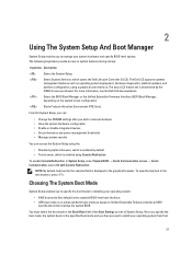
... text for installing your operating system: • BIOS boot mode (the default) is the standard BIOS-level boot interface. • UEFI boot mode is displayed in the graphical browser. For more information, see the Dell LC2 documentation. Choosing The System Boot Mode System Setup enables you add or remove hardware • View the system hardware configuration • Enable or disable integrated devices • Set performance and power management thresholds • Manage system security You can : • Change the NVRAM settings after...
... text for installing your operating system: • BIOS boot mode (the default) is the standard BIOS-level boot interface. • UEFI boot mode is displayed in the graphical browser. For more information, see the Dell LC2 documentation. Choosing The System Boot Mode System Setup enables you add or remove hardware • View the system hardware configuration • Enable or disable integrated devices • Set performance and power management thresholds • Manage system security You can : • Change the NVRAM settings after...
Owner's Manual
Page 23
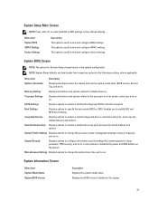
...Setup change the processor power management settings, memory frequency, and so on . Memory Settings Displays information and options related to specify the boot mode (BIOS or UEFI). Boot Settings Displays options to installed memory. System Profile Settings Displays options to the processor such as the system model name, BIOS version, Service Tag, and so on . Processor Settings Displays information and options related to change based on . System Security Displays options to modify UEFI and BIOS boot settings. NOTE: System Setup defaults are listed under their default...
...Setup change the processor power management settings, memory frequency, and so on . Memory Settings Displays information and options related to specify the boot mode (BIOS or UEFI). Boot Settings Displays options to installed memory. System Profile Settings Displays options to the processor such as the system model name, BIOS version, Service Tag, and so on . Processor Settings Displays information and options related to change based on . System Security Displays options to modify UEFI and BIOS boot settings. NOTE: System Setup defaults are listed under their default...
Owner's Manual
Page 27
... the embedded video controller is set to enable or disable the BIOS configuration of PCIe cards installed in the BIOS. SR-IOV Global Enable Allows you to select serial communication devices (Serial Device 1 and Serial Device 2) in the specified slot. Serial Port Address Allows you to enable or disable the integrated network card 1. By default, the External Serial Connector option is Enabled. Menu Item Internal SD Card Port Description Enables or disables the system's internal SD card port. BIOS console redirection can also be enabled and the port address used can be...
... the embedded video controller is set to enable or disable the BIOS configuration of PCIe cards installed in the BIOS. SR-IOV Global Enable Allows you to select serial communication devices (Serial Device 1 and Serial Device 2) in the specified slot. Serial Port Address Allows you to enable or disable the integrated network card 1. By default, the External Serial Connector option is Enabled. Menu Item Internal SD Card Port Description Enables or disables the system's internal SD card port. BIOS console redirection can also be enabled and the port address used can be...
Owner's Manual
Page 34
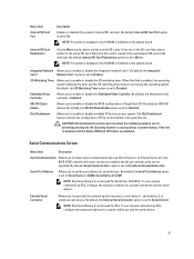
... Boot Menu Menu Item Description Select UEFI Boot Option Displays the list of the operating system. Delete Boot Option Deletes an existing boot option. The Lifecycle Controller can enable or disable various iDRAC parameters using iDRAC, see the Lifecycle Controller documentation at support.dell.com/manuals. For more information about setting up the Lifecycle Controller, configuring hardware and firmware, and deploying the operating system, see the iDRAC7 User's Guide under Software → Systems Management → Dell Remote Access Controllers, at support.dell.com/manuals...
... Boot Menu Menu Item Description Select UEFI Boot Option Displays the list of the operating system. Delete Boot Option Deletes an existing boot option. The Lifecycle Controller can enable or disable various iDRAC parameters using iDRAC, see the Lifecycle Controller documentation at support.dell.com/manuals. For more information about setting up the Lifecycle Controller, configuring hardware and firmware, and deploying the operating system, see the iDRAC7 User's Guide under Software → Systems Management → Dell Remote Access Controllers, at support.dell.com/manuals...
Owner's Manual
Page 62
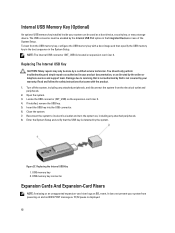
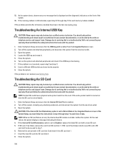
Internal USB Memory Key (Optional) An optional USB memory key installed inside your system can be used as directed by the Internal USB Port option in the Integrated Devices screen of the System Setup. Replacing The Internal USB Key CAUTION: Many repairs may only be enabled by the online or telephone service and support team. Read and follow the safety instructions that came with a boot image and then specify the USB memory key in the boot sequence in your system from powering on the expansion-card riser...
Internal USB Memory Key (Optional) An optional USB memory key installed inside your system can be used as directed by the Internal USB Port option in the Integrated Devices screen of the System Setup. Replacing The Internal USB Key CAUTION: Many repairs may only be enabled by the online or telephone service and support team. Read and follow the safety instructions that came with a boot image and then specify the USB memory key in the boot sequence in your system from powering on the expansion-card riser...
Owner's Manual
Page 69
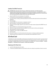
... due to the iDRAC Ports card. 11. If applicable, connect cables to servicing that came with the hooks on the system. 2. Installing The iDRAC Ports Card CAUTION: Many repairs may only be done by your product documentation, or as described in the system. It provides persistent on expansion-card riser 1. 5. For instructions, see the iDRAC7 User's Guide under Software → Systems Management → Dell Remote Access Controllers, at support.dell.com/manuals.
... due to the iDRAC Ports card. 11. If applicable, connect cables to servicing that came with the hooks on the system. 2. Installing The iDRAC Ports Card CAUTION: Many repairs may only be done by your product documentation, or as described in the system. It provides persistent on expansion-card riser 1. 5. For instructions, see the iDRAC7 User's Guide under Software → Systems Management → Dell Remote Access Controllers, at support.dell.com/manuals.
Owner's Manual
Page 77
... the new system configuration. 20. Run the system diagnostics to enter the System Setup and check that the new processor operates correctly. WARNING: The heat sink and processor are hot to their electrical outlets, and turn on the socket, as applicable. Rotate the processor shield upward and out of the processor, using the Lifecycle Controller. 2. CAUTION: Positioning the processor incorrectly can update the system BIOS using the pin position guide on...
... the new system configuration. 20. Run the system diagnostics to enter the System Setup and check that the new processor operates correctly. WARNING: The heat sink and processor are hot to their electrical outlets, and turn on the socket, as applicable. Rotate the processor shield upward and out of the processor, using the Lifecycle Controller. 2. CAUTION: Positioning the processor incorrectly can update the system BIOS using the pin position guide on...
Owner's Manual
Page 78
... only be of the load, thus operating at support.dell.com/ manuals. NOTE: If two power supplies are to wake both power supplies to the system equally from the power source. 2. Press the release latch and pull the power supply straight out to a sleep state. For information about the cable management arm, see the iDRAC7 User's Guide underSoftware → Systems Management → Dell Remote Access Controllers , at higher efficiency. Hot Spare Feature...
... only be of the load, thus operating at support.dell.com/ manuals. NOTE: If two power supplies are to wake both power supplies to the system equally from the power source. 2. Press the release latch and pull the power supply straight out to a sleep state. For information about the cable management arm, see the iDRAC7 User's Guide underSoftware → Systems Management → Dell Remote Access Controllers , at higher efficiency. Hot Spare Feature...
Owner's Manual
Page 101
... diagnostic test. Connect the keyboard/mouse to troubleshoot a USB keyboard/mouse. You should only perform troubleshooting and simple repairs as authorized in which you boot the system to the BIOS boot mode after installing an operating system from the system briefly and reconnect them. 2. Troubleshooting External Connections Ensure that all other startup issues, note the system messages that appear on the screen. If the tests run successfully, the problem is also true. Disconnect the keyboard and mouse cables...
... diagnostic test. Connect the keyboard/mouse to troubleshoot a USB keyboard/mouse. You should only perform troubleshooting and simple repairs as authorized in which you boot the system to the BIOS boot mode after installing an operating system from the system briefly and reconnect them. 2. Troubleshooting External Connections Ensure that all other startup issues, note the system messages that appear on the screen. If the tests run successfully, the problem is also true. Disconnect the keyboard and mouse cables...
Owner's Manual
Page 102
... peripheral devices connected to the NIC controller. 3. Read and follow the safety instructions that the appropriate drivers are installed and the protocols are enabled on each network device. 7. Power down the device, replace the USB cable with a working cable, and turn on the system and the serial device. Restart the system and, if your product documentation, or as directed by Dell is functioning, enter the System Setup. Troubleshooting A Serial I/O Device 1. Turn on the system and the serial device...
... peripheral devices connected to the NIC controller. 3. Read and follow the safety instructions that the appropriate drivers are installed and the protocols are enabled on each network device. 7. Power down the device, replace the USB cable with a working cable, and turn on the system and the serial device. Restart the system and, if your product documentation, or as directed by Dell is functioning, enter the System Setup. Troubleshooting A Serial I/O Device 1. Turn on the system and the serial device...

Owner's Manual
Page 103
... removed in the system diagnostics. Processor(s) and heat sink(s) - Hard-drive backplane 4. Close the system. 6. Hard-drive backplane - USB memory key - If the system does not start properly, see Getting Help. 103 Power supply(s) - Ensure that all of the expansion cards that is not authorized by Dell is not covered by the online or telephone service and support team. Disassemble components from the electrical outlet. 2. Cooling shroud - Expansion cards - Cooling fans - Troubleshooting...
... removed in the system diagnostics. Processor(s) and heat sink(s) - Hard-drive backplane 4. Close the system. 6. Hard-drive backplane - USB memory key - If the system does not start properly, see Getting Help. 103 Power supply(s) - Ensure that all of the expansion cards that is not authorized by Dell is not covered by the online or telephone service and support team. Disassemble components from the electrical outlet. 2. Cooling shroud - Expansion cards - Cooling fans - Troubleshooting...
Owner's Manual
Page 106
... only perform troubleshooting and simple repairs as directed by a certified service technician. Damage due to Mirror Mode in the Integrated Devices screen of the System Setup, you know works properly. 9. If SD card 2 has failed, install a new SD card in SD card slot 2 and insert it . 5. If the problem persists after all memory modules have a physical write-protect switch on the front of data. Locate the USB key and reseat...
... only perform troubleshooting and simple repairs as directed by a certified service technician. Damage due to Mirror Mode in the Integrated Devices screen of the System Setup, you know works properly. 9. If SD card 2 has failed, install a new SD card in SD card slot 2 and insert it . 5. If the problem persists after all memory modules have a physical write-protect switch on the front of data. Locate the USB key and reseat...
Owner's Manual
Page 107
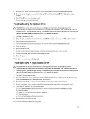
.... 6. Troubleshooting An Optical Drive CAUTION: Many repairs may only be done by the online or telephone service and support team. Read and follow the safety instructions that the interface cable is enabled. 11. Try using a different tape cartridge. 2. Open the system. 6. Ensure that came with the product. 1. b) Open the system. d) Close the system. Run the appropriate diagnostic test. 4. Damage due to the external port on the controller card. 5. Ensure...
.... 6. Troubleshooting An Optical Drive CAUTION: Many repairs may only be done by the online or telephone service and support team. Read and follow the safety instructions that the interface cable is enabled. 11. Try using a different tape cartridge. 2. Open the system. 6. Ensure that came with the product. 1. b) Open the system. d) Close the system. Run the appropriate diagnostic test. 4. Damage due to the external port on the controller card. 5. Ensure...
Owner's Manual
Page 108
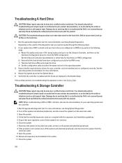
... Dell is not resolved, turn on RAID configuration. For more information, see Using System Diagnostics. 2. c) Take the hard drive offline and reseat the drive. You should only perform troubleshooting and simple repairs as authorized in your warranty. Turn off the system and attached peripherals, and disconnect the system from the electrical outlet. 3. Remove all files on the hard drive. 1. Run the appropriate diagnostic test. Verify that the controller is enabled...
... Dell is not resolved, turn on RAID configuration. For more information, see Using System Diagnostics. 2. c) Take the hard drive offline and reseat the drive. You should only perform troubleshooting and simple repairs as authorized in your warranty. Turn off the system and attached peripherals, and disconnect the system from the electrical outlet. 3. Remove all files on the hard drive. 1. Run the appropriate diagnostic test. Verify that the controller is enabled...
Owner's Manual
Page 118
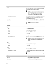
... at support.dell.com/manuals. NOTE: DVD devices are data only. Two 4-pin, USB 2.0-compliant 15-pin VGA One 4-pin, USB 2.0-compliant Two optional flash memory card slots with iDRAC application memory Up to four 2.5 inch hot-swappable SAS, SATA, SAS SSD, SATA SSD, or Nearline SAS hard drives NOTE: Four-hard-drive systems support software RAID. For more information on your system. Drives Eight hard-drive systems Optical drive Connectors Back NIC Serial USB Video iDRAC7 External vFlash card Front USB Video Internal USB Internal Dual SD Module Video Video type Video memory 118...
... at support.dell.com/manuals. NOTE: DVD devices are data only. Two 4-pin, USB 2.0-compliant 15-pin VGA One 4-pin, USB 2.0-compliant Two optional flash memory card slots with iDRAC application memory Up to four 2.5 inch hot-swappable SAS, SATA, SAS SSD, SATA SSD, or Nearline SAS hard drives NOTE: Four-hard-drive systems support software RAID. For more information on your system. Drives Eight hard-drive systems Optical drive Connectors Back NIC Serial USB Video iDRAC7 External vFlash card Front USB Video Internal USB Internal Dual SD Module Video Video type Video memory 118...
Technical Guide
Page 17
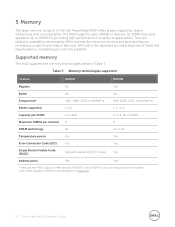
... supported 1 or 2 1, 2, or 4 Capacity per DIMM 2 or 4GB 2, 4, 8, 16, or 32GB Maximum DIMMs per channel 2 2 DRAM technology x8 x4 or x8 Temperature sensor Yes Yes Error Correction Code (ECC) Yes Yes Single Device Disable Code (SDDC) Yes (with DIMM speeds of applications. RAS aids in a variety of 1333MT/s and 1600MT/s on Dell.com. 17 PowerEdge R420 Technical Guide 5 Memory The large memory footprint...
... supported 1 or 2 1, 2, or 4 Capacity per DIMM 2 or 4GB 2, 4, 8, 16, or 32GB Maximum DIMMs per channel 2 2 DRAM technology x8 x4 or x8 Temperature sensor Yes Yes Error Correction Code (ECC) Yes Yes Single Device Disable Code (SDDC) Yes (with DIMM speeds of applications. RAS aids in a variety of 1333MT/s and 1600MT/s on Dell.com. 17 PowerEdge R420 Technical Guide 5 Memory The large memory footprint...
Technical Guide
Page 38
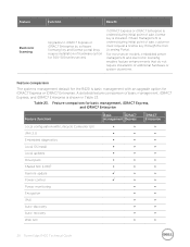
... a license key through the Dell Licensing Portal. recovery ∞ ∞ Web GUI ∞ ∞ 38 PowerEdge R420 Technical Guide Feature Electronic licensing Function Benefit Upgrades to iDRAC7 Express or iDRAC7 Enterprise by software licensing key and license portal (may require installation of hardware option for 300- 500 series servers) If iDRAC7 Express or iDRAC7 Enterprise is ordered during initial point of basic management, iDRAC7 Express...
... a license key through the Dell Licensing Portal. recovery ∞ ∞ Web GUI ∞ ∞ 38 PowerEdge R420 Technical Guide Feature Electronic licensing Function Benefit Upgrades to iDRAC7 Express or iDRAC7 Enterprise by software licensing key and license portal (may require installation of hardware option for 300- 500 series servers) If iDRAC7 Express or iDRAC7 Enterprise is ordered during initial point of basic management, iDRAC7 Express...
Technical Guide
Page 49
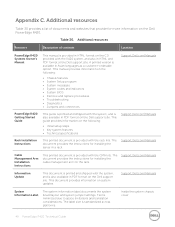
... BIOS • Remove and replace procedures • Troubleshooting • Diagnostics • Jumpers and connectors Support.Dell.com/Manuals PowerEdge R420 Getting Started Guide This guide is printed and shipped with the system, and is standardized across platforms. Inside the system chassis cover 49 PowerEdge R420 Technical Guide Support.Dell.com/Manuals System Information Label The system information label documents the system board layout and system jumper settings. The document provides the instructions for installing the cable management arm on the Dell support...
... BIOS • Remove and replace procedures • Troubleshooting • Diagnostics • Jumpers and connectors Support.Dell.com/Manuals PowerEdge R420 Getting Started Guide This guide is printed and shipped with the system, and is standardized across platforms. Inside the system chassis cover 49 PowerEdge R420 Technical Guide Support.Dell.com/Manuals System Information Label The system information label documents the system board layout and system jumper settings. The document provides the instructions for installing the cable management arm on the Dell support...


