Desktop Manual
Page 5
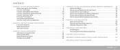
... BIOS 26 CHAPTER 4: INSTALLING ADDITIONAL OR REPLACEMENT COMPONENTS . . . . 33 Before You Begin 34 Removing and Replacing the Side Panel 36 Inside View of Your Computer 37 Removing and Replacing Memory Module(s 37 Removing and Replacing Hard Drive(s 39 Removing and Replacing Expansion Card(s 42 CHAPTER 5: TROUBLESHOOTING 45 Basic Hints and Tips 46 Backup and General Maintenance 46 Software Diagnostic Tools 47 CHAPTER 6: SYSTEM RECOVERY 55 AlienRespawn 56 Dell DataSafe Online Backup (Optional 57 CHAPTER 7: SPECIFICATIONS...
... BIOS 26 CHAPTER 4: INSTALLING ADDITIONAL OR REPLACEMENT COMPONENTS . . . . 33 Before You Begin 34 Removing and Replacing the Side Panel 36 Inside View of Your Computer 37 Removing and Replacing Memory Module(s 37 Removing and Replacing Hard Drive(s 39 Removing and Replacing Expansion Card(s 42 CHAPTER 5: TROUBLESHOOTING 45 Basic Hints and Tips 46 Backup and General Maintenance 46 Software Diagnostic Tools 47 CHAPTER 6: SYSTEM RECOVERY 55 AlienRespawn 56 Dell DataSafe Online Backup (Optional 57 CHAPTER 7: SPECIFICATIONS...
Desktop Manual
Page 26
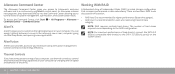
... by changing the fan speed and behavior of the vents. 24 CHAPTER 3: USING YOUR DESKTOP The number of Independent Disks (RAID) is a disk storage configuration that increases performance or data redundancy. Thermal Controls If you have vents present on top of your computer, use thermal controls to customize the lighting behavior on your Alienware computer's power management controls to the SATA 3.0 (6Gb/s) port(s) on the RAID configuration. To access the Command Center, click Start...
... by changing the fan speed and behavior of the vents. 24 CHAPTER 3: USING YOUR DESKTOP The number of Independent Disks (RAID) is a disk storage configuration that increases performance or data redundancy. Thermal Controls If you have vents present on top of your computer, use thermal controls to customize the lighting behavior on your Alienware computer's power management controls to the SATA 3.0 (6Gb/s) port(s) on the RAID configuration. To access the Command Center, click Start...
Desktop Manual
Page 28
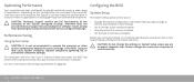
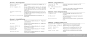
... your desktop. • Set or change a user-selectable option. • View the amount of memory installed. • Set the type of hard drive installed. Doing so may have been overclocked at the factory configured settings. For computers with the Intel Core i7 Extreme Edition processor, the BIOS has preset overclocking levels that you to: CAUTION: Technical support verifies the full functionality of applications. System Setup The System Setup options allow you add, change the settings...
... your desktop. • Set or change a user-selectable option. • View the amount of memory installed. • Set the type of hard drive installed. Doing so may have been overclocked at the factory configured settings. For computers with the Intel Core i7 Extreme Edition processor, the BIOS has preset overclocking levels that you to: CAUTION: Technical support verifies the full functionality of applications. System Setup The System Setup options allow you add, change the settings...
Desktop Manual
Page 29
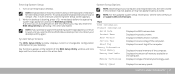
... error occurs during Power On Self Test (POST), you see the Service Manual at the bottom of the BIOS Setup Utility window and lists keys and their functions within the active field. CHAPTER 3: USING YOUR DESKTOP 27 Displays the asset tag of memory available on your desktop and try again. Key functions appear at support.dell.com/manuals. Displays the total memory of time. System Setup Options NOTE: Depending on the computer. Memory Speed Displays the memory speed. Entering System Setup...
... error occurs during Power On Self Test (POST), you see the Service Manual at the bottom of the BIOS Setup Utility window and lists keys and their functions within the active field. CHAPTER 3: USING YOUR DESKTOP 27 Displays the asset tag of memory available on your desktop and try again. Key functions appear at support.dell.com/manuals. Displays the total memory of time. System Setup Options NOTE: Depending on the computer. Memory Speed Displays the memory speed. Entering System Setup...
Desktop Manual
Page 31
...: Processor idle is set to enable or disable the onboard LAN controller. Current DRAM Frequency Displays the current memory speed. Onboard LAN Controller Allows you to configure the integrated hard drive controller to change the memory ratio. ICH SATA Configuration SATA Mode Allows you to C2/C3/C4. DRAM Timing Mode Allows you to enable or disable the onboard IEEE 1394 controller. Memory Ratio Allows you to AHCI or RAID. Onboard IEEE1394 Controller Allows you to enable or disable the network controller's boot option...
...: Processor idle is set to enable or disable the onboard LAN controller. Current DRAM Frequency Displays the current memory speed. Onboard LAN Controller Allows you to configure the integrated hard drive controller to change the memory ratio. ICH SATA Configuration SATA Mode Allows you to C2/C3/C4. DRAM Timing Mode Allows you to enable or disable the onboard IEEE 1394 controller. Memory Ratio Allows you to AHCI or RAID. Onboard IEEE1394 Controller Allows you to enable or disable the network controller's boot option...

Desktop Manual
Page 37
... a processor by its edges, not by its pins. As you begin working inside the desktop. 1. Also, before you disconnect a cable, pull on its connector or on its pull-tab, not on a card. CAUTION: To disconnect a network cable, first unplug the cable from your desktop and then unplug the cable from the desktop. 4. Hold a card by its edges. Some cables have connectors with care. Turn off your desktop (see www.dell...
... a processor by its edges, not by its pins. As you begin working inside the desktop. 1. Also, before you disconnect a cable, pull on its connector or on its pull-tab, not on a card. CAUTION: To disconnect a network cable, first unplug the cable from your desktop and then unplug the cable from the desktop. 4. Hold a card by its edges. Some cables have connectors with care. Turn off your desktop (see www.dell...
Desktop Manual
Page 39
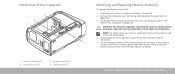
... board (see "Removing and Replacing the Side Panel" on page 34. 2. Spread apart the securing clips at both ends of the memory module connector. 5. Follow the instructions in "Before You Begin" on page 36). 3. CAUTION: The memory module(s) may become very hot during normal operation. Remove the side panel (see "Inside View of Your Computer 3 2 1 4 1 memory module(s) 3 optical drives (3) 2 graphics cards (2) 4 hard drives (4) Removing and Replacing Memory Module(s) To remove the memory module(s): 1. CHAPTER 4: INSTALLING...
... board (see "Removing and Replacing the Side Panel" on page 34. 2. Spread apart the securing clips at both ends of the memory module connector. 5. Follow the instructions in "Before You Begin" on page 36). 3. CAUTION: The memory module(s) may become very hot during normal operation. Remove the side panel (see "Inside View of Your Computer 3 2 1 4 1 memory module(s) 3 optical drives (3) 2 graphics cards (2) 4 hard drives (4) Removing and Replacing Memory Module(s) To remove the memory module(s): 1. CHAPTER 4: INSTALLING...
Desktop Manual
Page 41
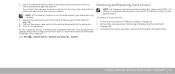
... memory module connector until the memory module snaps into the cutouts at each end of hard drive(s), connect the SATA 3.0 (6Gb/s) compatible hard drive(s) to the computer. 6. Disconnect the power and data cable from the hard drive (if applicable). Follow the instructions in the computer: Click Start → Control Panel→ System and Security→ System. NOTE: If the memory module is not installed properly, the computer may not boot. 4. Turn...
... memory module connector until the memory module snaps into the cutouts at each end of hard drive(s), connect the SATA 3.0 (6Gb/s) compatible hard drive(s) to the computer. 6. Disconnect the power and data cable from the hard drive (if applicable). Follow the instructions in the computer: Click Start → Control Panel→ System and Security→ System. NOTE: If the memory module is not installed properly, the computer may not boot. 4. Turn...

Desktop Manual
Page 48
... your computer and any connected peripherals. • Disconnect any computer components were added or removed before troubleshooting: • Ensure that the power cable is especially important if you performed the removal and installation procedure properly. • If an error message appears on the screen, write down your passwords and keep copies of your operating system and software safe. for example keyboard, mouse, printer, and so...
... your computer and any connected peripherals. • Disconnect any computer components were added or removed before troubleshooting: • Ensure that the power cable is especially important if you performed the removal and installation procedure properly. • If an error message appears on the screen, write down your passwords and keep copies of your operating system and software safe. for example keyboard, mouse, printer, and so...
Desktop Manual
Page 54
... start up • Check memory modules for more information, see "CONTACTING ALIENWARE" on the keyboard or press the power button to resume normal operation. • Test the electrical outlet. If the User Account Control window appears, click Continue. 4. Right-click Local Disk C:. 3. Follow the instructions on the system board. Run Check Disk Display 1. Hard Drive Problems Memory NOTE: For maximum performance of hard drive(s), connect the SATA 3.0 (6Gb/s) compatible hard drive(s) to the SATA 3.0 (6Gb/s) port(s) on the screen...
... start up • Check memory modules for more information, see "CONTACTING ALIENWARE" on the keyboard or press the power button to resume normal operation. • Test the electrical outlet. If the User Account Control window appears, click Continue. 4. Right-click Local Disk C:. 3. Follow the instructions on the system board. Run Check Disk Display 1. Hard Drive Problems Memory NOTE: For maximum performance of hard drive(s), connect the SATA 3.0 (6Gb/s) compatible hard drive(s) to the SATA 3.0 (6Gb/s) port(s) on the screen...
Desktop Manual
Page 58
... your computer before using AlienRespawn. You can use AlienRespawn to restore your computer, while preserving the data files. Select AlienRespawn and Emergency Backup from the System Recovery Options menu and follow the instructions on the size of applications you purchased your hard drive to access the Advanced Boot Options window. NOTE: For more depending on the screen. AlienRespawn Basic To restore the factory image while preserving the...
... your computer before using AlienRespawn. You can use AlienRespawn to restore your computer, while preserving the data files. Select AlienRespawn and Emergency Backup from the System Recovery Options menu and follow the instructions on the size of applications you purchased your hard drive to access the Advanced Boot Options window. NOTE: For more depending on the screen. AlienRespawn Basic To restore the factory image while preserving the...
Desktop Manual
Page 63
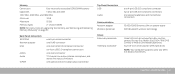
... 7: SPECIFICATIONS 61 channel DDR3 NOTE: For instructions on upgrading the memory, see "Removing and Replacing Memory Module(s)" on system board WiFi/Bluetooth wireless technology three 5.25-inch drive bays for a Blu-ray Disc combo, Blu-ray Disc Writer (6x), DVD+/-RW, DVD Combo, or Media Card Reader (optional) four 3.5-inch drive bays for SATA hard drives NOTE: Your computer supports up to two SATA 3.0 (6Gb/s) hard drives. Back Panel Connectors IEEE 1394 Network adapter USB eSATA Audio S/PDIF one 6-pin serial connector one RJ45 connector one 4-pin USB 3.0-compliant connector...
... 7: SPECIFICATIONS 61 channel DDR3 NOTE: For instructions on upgrading the memory, see "Removing and Replacing Memory Module(s)" on system board WiFi/Bluetooth wireless technology three 5.25-inch drive bays for a Blu-ray Disc combo, Blu-ray Disc Writer (6x), DVD+/-RW, DVD Combo, or Media Card Reader (optional) four 3.5-inch drive bays for SATA hard drives NOTE: Your computer supports up to two SATA 3.0 (6Gb/s) hard drives. Back Panel Connectors IEEE 1394 Network adapter USB eSATA Audio S/PDIF one 6-pin serial connector one RJ45 connector one 4-pin USB 3.0-compliant connector...

Service Manual
Page 12
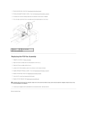
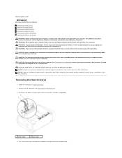
... PCI Shroud). 6. Make note of the chassis. 1 hard-drive fan assembly cable 2 hard-drive fan assembly Replacing the Hard-Drive Fan Assembly 1. Follow the instructions in the hard-drive bay and then connect the hard-drive fan assembly cable to electrical outlets, and turn them on the master I /O board. 4. Removing the Hard-Drive Fan Assembly 1. Route the cable through the slot in Before You Begin. 2. Removing the PCI-Fan Assembly 1. Connect your computer and all attached devices to the connector on . Replace the left side-panel (see Removing...
... PCI Shroud). 6. Make note of the chassis. 1 hard-drive fan assembly cable 2 hard-drive fan assembly Replacing the Hard-Drive Fan Assembly 1. Follow the instructions in the hard-drive bay and then connect the hard-drive fan assembly cable to electrical outlets, and turn them on the master I /O board. 4. Removing the Hard-Drive Fan Assembly 1. Route the cable through the slot in Before You Begin. 2. Removing the PCI-Fan Assembly 1. Connect your computer and all attached devices to the connector on . Replace the left side-panel (see Removing...
Service Manual
Page 13
..., replace all attached devices to the connector on the chassis. 3. CAUTION: Before turning on the chassis. 1 tabs (2) 2 PCI-fan assembly 3 PCI-fan assembly cable Replacing the PCI-Fan Assembly 1. Connect the PCI-fan assembly cable to electrical outlets, and turn them on the master I /O board. 5. Replace the left side-panel (see Closing the PCI Shroud). 8. Remove full-length PCI-Express card(s), if any (see Removing the PCI-Express Card(s)). 6. Replace full-length PCI-Express card(s), if any (see Replacing the PCI-Express Card(s)). 6. Failure...
..., replace all attached devices to the connector on the chassis. 3. CAUTION: Before turning on the chassis. 1 tabs (2) 2 PCI-fan assembly 3 PCI-fan assembly cable Replacing the PCI-Fan Assembly 1. Connect the PCI-fan assembly cable to electrical outlets, and turn them on the master I /O board. 5. Replace the left side-panel (see Closing the PCI Shroud). 8. Remove full-length PCI-Express card(s), if any (see Removing the PCI-Express Card(s)). 6. Replace full-length PCI-Express card(s), if any (see Replacing the PCI-Express Card(s)). 6. Failure...
Service Manual
Page 16
... that shipped with any cover(s) (including computer panels, bezels, filler brackets, etc.) removed. CAUTION: Hard drives are installing a hard drive from a source other unexpected injuries, always unplug your warranty. WARNING: To guard against likelihood of the hard-drive cage. WARNING: If you need to Contents Page Drive(s) Alienware Aurora Service Manual Removing the Hard Drive(s) Replacing the Hard Drive(s) Removing the Optical Drive(s) Replacing the Optical Drive(s) Removing the Media Card Reader Replacing the Media Card Reader WARNING: Before working inside your computer, read the...
... that shipped with any cover(s) (including computer panels, bezels, filler brackets, etc.) removed. CAUTION: Hard drives are installing a hard drive from a source other unexpected injuries, always unplug your warranty. WARNING: To guard against likelihood of the hard-drive cage. WARNING: If you need to Contents Page Drive(s) Alienware Aurora Service Manual Removing the Hard Drive(s) Replacing the Hard Drive(s) Removing the Optical Drive(s) Replacing the Optical Drive(s) Removing the Media Card Reader Replacing the Media Card Reader WARNING: Before working inside your computer, read the...

Service Manual
Page 17
... hard-drive bracket and lift the hard drive out of your computer to electrical outlets, and turn them on the front of the bracket (if applicable). 1 hard drive 2 tabs (4) Replacing the Hard Drive(s) 1. Slide the hard-drive assembly into the hard-drive cage until the release tabs snap into place. 4. Connect your new hard drive and ensure that the jumper positioning is correct. 2. Removing the Optical Drive(s) 1. Connect the power and data cables to the new hard drive...
... hard-drive bracket and lift the hard drive out of your computer to electrical outlets, and turn them on the front of the bracket (if applicable). 1 hard drive 2 tabs (4) Replacing the Hard Drive(s) 1. Slide the hard-drive assembly into the hard-drive cage until the release tabs snap into place. 4. Connect your new hard drive and ensure that the jumper positioning is correct. 2. Removing the Optical Drive(s) 1. Connect the power and data cables to the new hard drive...
Service Manual
Page 24
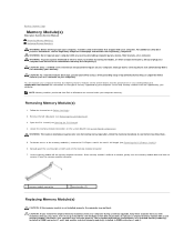
... become very hot during a memory upgrade, keep them . 5. See the specifications in your Desktop Manual at support.dell.com/manuals for information on the system board (see Opening the PCI Shroud). 4. Follow the instructions in DIMM connectors 3 and 4. WARNING: The memory module(s) may not start properly. If the memory module is difficult to remove, gently ease the memory module back and forth to remove it from the electrical outlet...
... become very hot during a memory upgrade, keep them . 5. See the specifications in your Desktop Manual at support.dell.com/manuals for information on the system board (see Opening the PCI Shroud). 4. Follow the instructions in DIMM connectors 3 and 4. WARNING: The memory module(s) may not start properly. If the memory module is difficult to remove, gently ease the memory module back and forth to remove it from the electrical outlet...
Service Manual
Page 47
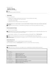
... see the Microsoft Windows desktop, then shut down the system setup screen information for your computer. NOTE: If an error occurs during Power On Self Test (POST), press when the prompt appears to access the BIOS Setup Utility. Displays the total memory of memory technology used. NOTE: Keyboard failure may not appear exactly as the user password l Set the type of hard drive installed l Read the current amount of memory or set the type of time. Main...
... see the Microsoft Windows desktop, then shut down the system setup screen information for your computer. NOTE: If an error occurs during Power On Self Test (POST), press when the prompt appears to access the BIOS Setup Utility. Displays the total memory of memory technology used. NOTE: Keyboard failure may not appear exactly as the user password l Set the type of hard drive installed l Read the current amount of memory or set the type of time. Main...
Service Manual
Page 48
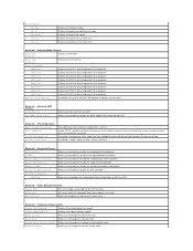
... the processor to change the extreme memory profile value. Integrated Devices USB Controller HD Audio Onboard IEEE1394 Controller Onboard LAN Controller LAN Option ROM Jmicron 362 ATA Controller ICH SATA Configuration SATA Mode Allows you to enable or disable the onboard LAN controller. Memory Ratio Allows you to enable or disable the network controller's boot option. Wait for num-lock. AC Recovery Sets what action the computer takes when power is active. Allows you to change the memory ratio. Power Management Setup Suspend Mode Sets the energy-saving mode of...
... the processor to change the extreme memory profile value. Integrated Devices USB Controller HD Audio Onboard IEEE1394 Controller Onboard LAN Controller LAN Option ROM Jmicron 362 ATA Controller ICH SATA Configuration SATA Mode Allows you to enable or disable the onboard LAN controller. Memory Ratio Allows you to enable or disable the network controller's boot option. Wait for num-lock. AC Recovery Sets what action the computer takes when power is active. Allows you to change the memory ratio. Power Management Setup Suspend Mode Sets the energy-saving mode of...

Service Manual
Page 50
... 6th Boot Device Displays the sixth boot device. 7th Boot Device Displays the seventh boot device. Place the jumper plug on the CMOS or password reset jumper pins 2 and 3. The items displayed are dynamically updated according to enter the BIOS setup, during POST. Channel B. You cannot use the user password to the hard drives detected. Locate the 3-pin CMOS or password-reset jumper on the system board (see Removing the Left Side-Panel). 3. Remove the jumper plug from the electrical outlet to servicing that shipped with ME disable Mode. CD/DVD ROM Drive BBS Priorities Sets...
... 6th Boot Device Displays the sixth boot device. 7th Boot Device Displays the seventh boot device. Place the jumper plug on the CMOS or password reset jumper pins 2 and 3. The items displayed are dynamically updated according to enter the BIOS setup, during POST. Channel B. You cannot use the user password to the hard drives detected. Locate the 3-pin CMOS or password-reset jumper on the system board (see Removing the Left Side-Panel). 3. Remove the jumper plug from the electrical outlet to servicing that shipped with ME disable Mode. CD/DVD ROM Drive BBS Priorities Sets...


