Owner's Manual
Page 7
System Setup Options 104 Boot Sequence 107 Clearing Forgotten Passwords 109 Clearing CMOS Settings 110 Cleaning Your Computer 110 Computer, Keyboard, and Monitor 110 Mouse 111 Floppy Drive 111 CDs and DVDs 111 Dell Technical Support Policy (U.S. Only 112 Class A 113 Class B 113 FCC Identification Information 114 Contacting Dell 114 Index 133 Contents 7 Only 112 Definition of "Dell-Installed" Software and Peripherals 112 Definition of "Third-Party" Software and Peripherals 112 FCC Notices (U.S.
System Setup Options 104 Boot Sequence 107 Clearing Forgotten Passwords 109 Clearing CMOS Settings 110 Cleaning Your Computer 110 Computer, Keyboard, and Monitor 110 Mouse 111 Floppy Drive 111 CDs and DVDs 111 Dell Technical Support Policy (U.S. Only 112 Class A 113 Class B 113 FCC Identification Information 114 Contacting Dell 114 Index 133 Contents 7 Only 112 Definition of "Dell-Installed" Software and Peripherals 112 Definition of "Third-Party" Software and Peripherals 112 FCC Notices (U.S.

Owner's Manual
Page 27
.... 3 Use the up - Configuring Your Computer for the volume, and press . In a RAID level 1 configuration, the size of equal size. NOTE: If your computer currently boots to RAID and you delete the RAID volume in the Intel RAID Option ROM utility, your computer to RAID-enabled mode (see "System Setup Options..." on the main Intel RAID Option ROM utility screen. 11 Use the up - and right-arrow keys to exit system setup and resume the boot process. NOTE: For more than two hard drives available, press the up - and right-arrow keys to highlight Save/Exit, and press to highlight ...
.... 3 Use the up - Configuring Your Computer for the volume, and press . In a RAID level 1 configuration, the size of equal size. NOTE: If your computer currently boots to RAID and you delete the RAID volume in the Intel RAID Option ROM utility, your computer to RAID-enabled mode (see "System Setup Options..." on the main Intel RAID Option ROM utility screen. 11 Use the up - and right-arrow keys to exit system setup and resume the boot process. NOTE: For more than two hard drives available, press the up - and right-arrow keys to highlight Save/Exit, and press to highlight ...
Owner's Manual
Page 47
...Memory modules are off and the system does not start, there may be a problem with the power supply or with the processor. successfully boots to help you have identified a faulty module or reinstalled all of the diagnostic lights are detected, but a memory failure has occurred. ... memory modules installed, remove the modules, reinstall one module (see ""Installing Memory" on page 67). • If the problem persists, contact Dell for technical assistance. Your computer has four lights labeled "1," "2," "3," and "4" on the front panel to the operating system. Light Pattern Problem...
...Memory modules are off and the system does not start, there may be a problem with the power supply or with the processor. successfully boots to help you have identified a faulty module or reinstalled all of the diagnostic lights are detected, but a memory failure has occurred. ... memory modules installed, remove the modules, reinstall one module (see ""Installing Memory" on page 67). • If the problem persists, contact Dell for technical assistance. Your computer has four lights labeled "1," "2," "3," and "4" on the front panel to the operating system. Light Pattern Problem...

Owner's Manual
Page 49
...from a device (such as the floppy drive or hard drive), check the device to boot from the computer for resource conflicts (see "Cards" on your computer. • If the problem persists, contact Dell for technical assistance. Another failure has occurred. • Ensure that the cables are ...properly connected to the system board from the hard drive, CD drive, and DVD drive (see "System Setup" on page 103) to make sure the boot sequence is attempting to...
...from a device (such as the floppy drive or hard drive), check the device to boot from the computer for resource conflicts (see "Cards" on your computer. • If the problem persists, contact Dell for technical assistance. Another failure has occurred. • Ensure that the cables are ...properly connected to the system board from the hard drive, CD drive, and DVD drive (see "System Setup" on page 103) to make sure the boot sequence is attempting to...
Owner's Manual
Page 51
...the tests you want to increase the possibility of tracing the problem quickly. Advanced Troubleshooting 51 If you cannot resolve the error condition, contact Dell (see page 51). If you wait too long and the operating system logo appears, continue to select a test based on the screen....run . Tests a specific device. Write down your computer (see page 57) and try again. 3 When the boot device list appears, highlight Boot to Utility Partition and press . 4 When the Dell Diagnostics Main Menu appears, select the test you to 20 minutes and requires no interaction on (or restart) your ...
...the tests you want to increase the possibility of tracing the problem quickly. Advanced Troubleshooting 51 If you cannot resolve the error condition, contact Dell (see page 51). If you wait too long and the operating system logo appears, continue to select a test based on the screen....run . Tests a specific device. Write down your computer (see page 57) and try again. 3 When the boot device list appears, highlight Boot to Utility Partition and press . 4 When the Dell Diagnostics Main Menu appears, select the test you to 20 minutes and requires no interaction on (or restart) your ...

Owner's Manual
Page 62
... information on the computer. Use to identify your computer when you use the power button to turn on booting to the hard drive. The hard drive activity light is recommended that you access the Dell Support website or call technical support. 60 Removing and Installing Parts Press to the system. It is...
... information on the computer. Use to identify your computer when you use the power button to turn on booting to the hard drive. The hard drive activity light is recommended that you access the Dell Support website or call technical support. 60 Removing and Installing Parts Press to the system. It is...

Owner's Manual
Page 79
... interface cable and configure them for the cable select setting, the device attached to the last connector on the interface cable is the master or boot device (drive 0), and the device attached to the connector labeled "IDE" on the system board. CD/DVD drive(s) FlexBay for optional floppy drive or Media...
... interface cable and configure them for the cable select setting, the device attached to the last connector on the interface cable is the master or boot device (drive 0), and the device attached to the connector labeled "IDE" on the system board. CD/DVD drive(s) FlexBay for optional floppy drive or Media...

Owner's Manual
Page 103
amber light - If the system cannot boot and there is not detecting a physical connection to the network. orange light - A good connection exists between a 10-Mbps network and the computer. solid green for ...
amber light - If the system cannot boot and there is not detecting a physical connection to the network. orange light - A good connection exists between a 10-Mbps network and the computer. solid green for ...

Owner's Manual
Page 107
...Identifies and defines the SATA controller settings for the integrated video controller. Enables or disables the onboard audio controller. Memory Info Date/Time Boot Sequence Indicates amount of installed memory, memory speed, channel mode (dual or single), and type of 1MB and 8MB, this field ... the FLOPPY connector on the computer. Onboard Devices Integrated NIC Controller Integrated Audio Controller You can set the NIC to boot from a network server. If a boot routine is primary when two video controllers are present on the system board as Off, USB, Internal, or Read Only...
...Identifies and defines the SATA controller settings for the integrated video controller. Enables or disables the onboard audio controller. Memory Info Date/Time Boot Sequence Indicates amount of installed memory, memory speed, channel mode (dual or single), and type of 1MB and 8MB, this field ... the FLOPPY connector on the computer. Onboard Devices Integrated NIC Controller Integrated Audio Controller You can set the NIC to boot from a network server. If a boot routine is primary when two video controllers are present on the system board as Off, USB, Internal, or Read Only...

Owner's Manual
Page 109
... computer generates an error message. • Hard Drive - This setting restores the computer's default settings. This option allows you to change the boot sequence for most components, however, system memory remains active. On is in the drive, or if the CD has no floppy drive installed in...where the power is enabled, the computer can be powered up remotely from Suspend. This option involves the rightmost bank of each key. Boot Sequence This feature allows you to specify the function keys to On (default), this option activates the cursor-control functions labeled on the ...
... computer generates an error message. • Hard Drive - This setting restores the computer's default settings. This option allows you to change the boot sequence for most components, however, system memory remains active. On is in the drive, or if the CD has no floppy drive installed in...where the power is enabled, the computer can be powered up remotely from Suspend. This option involves the rightmost bank of each key. Boot Sequence This feature allows you to specify the function keys to On (default), this option activates the cursor-control functions labeled on the ...

Owner's Manual
Page 110
...NOTE: Write down your computer (see the Microsoft Windows desktop. and down the list. 108 Appendix NOTE: To boot to be used for the current boot only. The Boot Device Menu appears, listing all available boot devices. To ensure that is bootable, check the device documentation. • USB Flash Device - Each device ... next to OFF in the upper-right corner of the device that a device is to a USB device, the device must be bootable. NOTE: To boot to a USB device, the device must first set Diskette Drive to it . 3 Press the up or down -arrow keys to access the menu. NOTE...
...NOTE: Write down your computer (see the Microsoft Windows desktop. and down the list. 108 Appendix NOTE: To boot to be used for the current boot only. The Boot Device Menu appears, listing all available boot devices. To ensure that is bootable, check the device documentation. • USB Flash Device - Each device ... next to OFF in the upper-right corner of the device that a device is to a USB device, the device must be bootable. NOTE: To boot to a USB device, the device must first set Diskette Drive to it . 3 Press the up or down -arrow keys to access the menu. NOTE...

Owner's Manual
Page 135
Index A audio. See sound B battery problems, 31 replacing, 95 BIOS, 103 boot sequence about, 107 changing, 108 option settings, 107 booting to a USB device, 108 C cards installing PCI, 70 PCI, 69 PCI Express, 69 PCI Express slots, 62 PCI slots, 62 removing ...DVDs general information, 18 helpful tips, 20 how to, 18 cover removing, 62 replacing, 96 D Dell contacting, 114 support policy, 112 support site, 10 Dell Diagnostics, 50 Dell Premier Support website, 9 diagnostic lights, 47 diagnostics Dell, 50 lights, 47, 60 documentation End User License Agreement, 9 ergonomics, 9 online, 10 Index 133...
Index A audio. See sound B battery problems, 31 replacing, 95 BIOS, 103 boot sequence about, 107 changing, 108 option settings, 107 booting to a USB device, 108 C cards installing PCI, 70 PCI, 69 PCI Express, 69 PCI Express slots, 62 PCI slots, 62 removing ...DVDs general information, 18 helpful tips, 20 how to, 18 cover removing, 62 replacing, 96 D Dell contacting, 114 support policy, 112 support site, 10 Dell Diagnostics, 50 Dell Premier Support website, 9 diagnostic lights, 47 diagnostics Dell, 50 lights, 47, 60 documentation End User License Agreement, 9 ergonomics, 9 online, 10 Index 133...

Owner's Manual
Page 138
...100 environmental, 102 expansion bus, 100 memory, 99 physical, 102 power, 102 processor, 99 technical, 99 video, 100 standby mode, 23 support contacting Dell, 114 policy, 112 support website, 10 system board, 65 System Restore, 53-54 system setup about, 103 entering, 103 options, 104 screens, 103 ... diagnostic lights, 47 Hardware Troubleshooter, 53 Help and Support Center, 11 troubleshooting (continued) restore to previous state, 53-54 tips, 31 U USB booting to devices, 108 connectors, 60-61 V vents, 60 front panel, 60 VGA connector, 62 video connector, 62 volume adjusting, 43 W warranty ...
...100 environmental, 102 expansion bus, 100 memory, 99 physical, 102 power, 102 processor, 99 technical, 99 video, 100 standby mode, 23 support contacting Dell, 114 policy, 112 support website, 10 system board, 65 System Restore, 53-54 system setup about, 103 entering, 103 options, 104 screens, 103 ... diagnostic lights, 47 Hardware Troubleshooter, 53 Help and Support Center, 11 troubleshooting (continued) restore to previous state, 53-54 tips, 31 U USB booting to devices, 108 connectors, 60-61 V vents, 60 front panel, 60 VGA connector, 62 video connector, 62 volume adjusting, 43 W warranty ...

Service Manual
Page 5
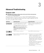
... long and the operating system logo appears, continue to proceed. 6. Type 1 to start -up, the computer boots according to Contents Page Advanced Troubleshooting Dell™ Dimension™ 3100/E310 Service Manual Dell Diagnostics System Lights Diagnostic Lights Beep Codes Dell Diagnostics CAUTION: Before you begin any of the procedures in this section, follow the safety instructions...
... long and the operating system logo appears, continue to proceed. 6. Type 1 to start -up, the computer boots according to Contents Page Advanced Troubleshooting Dell™ Dimension™ 3100/E310 Service Manual Dell Diagnostics System Lights Diagnostic Lights Beep Codes Dell Diagnostics CAUTION: Before you begin any of the procedures in this section, follow the safety instructions...

Service Manual
Page 6
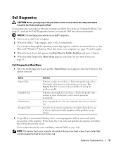
... computer is identified. Check the diagnostic lights to 20 minutes and requires no video during POST incorrectly installed. If you contact Dell, technical support will ask for the selected device. Close the test screen to return to increase the possibility of all the components... running a test, or a device on the keyboard to see if the specific problem is required. If the computer does not boot, contact Dell for technical assistance. Dell Diagnostics Main Menu 1. This test typically takes 1 hour or more information. The device list may indicate a computer problem. Solid ...
... computer is identified. Check the diagnostic lights to 20 minutes and requires no video during POST incorrectly installed. If you contact Dell, technical support will ask for the selected device. Close the test screen to return to increase the possibility of all the components... running a test, or a device on the keyboard to see if the specific problem is required. If the computer does not boot, contact Dell for technical assistance. Dell Diagnostics Main Menu 1. This test typically takes 1 hour or more information. The device list may indicate a computer problem. Solid ...

Service Manual
Page 7
...has occurred. l If available, install properly working electrical outlet. If the problem persists, reinstall the card that it is not identified, contact Dell for technical assistance. l The operating system is identified. Your computer has four lights labeled "1," "2," "3," and "4" on your screen identifying... malfunctions, the color and sequence of the same type into a working memory of the diagnostic lights are properly connected to boot from the computer for technical assistance. 1. l If you have two or more memory modules installed, remove the modules, ...
...has occurred. l If available, install properly working electrical outlet. If the problem persists, reinstall the card that it is not identified, contact Dell for technical assistance. l The operating system is identified. Your computer has four lights labeled "1," "2," "3," and "4" on your screen identifying... malfunctions, the color and sequence of the same type into a working memory of the diagnostic lights are properly connected to boot from the computer for technical assistance. 1. l If you have two or more memory modules installed, remove the modules, ...

Service Manual
Page 8
..., all of the diagnostic lights turn on your Owner's Manual. Reseat the processor (see "System Setup") to make sure the boot sequence is correct for the devices installed on then off before the system starts. One possible beep code (code 1-3-1) consists of ... Unplug the power supply and check the 4-pin processor power cable connection (see "Power Problems" in your computer beeps during start , contact Dell for video ROM failure 4-2-1 No timer tick 4-2-2 Shutdown failure 4-2-3 Gate A20 failure 4-2-4 Unexpected interrupt in protected mode 4-3-1 Memory failure above ...
..., all of the diagnostic lights turn on your Owner's Manual. Reseat the processor (see "System Setup") to make sure the boot sequence is correct for the devices installed on then off before the system starts. One possible beep code (code 1-3-1) consists of ... Unplug the power supply and check the 4-pin processor power cable connection (see "Power Problems" in your computer beeps during start , contact Dell for video ROM failure 4-2-1 No timer tick 4-2-2 Shutdown failure 4-2-3 Gate A20 failure 4-2-4 Unexpected interrupt in protected mode 4-3-1 Memory failure above ...

Service Manual
Page 22
... interface cable and configure them for the cable select setting, the device attached to the last connector on the interface cable is the master or boot device (drive 0), and the device attached to the middle connector on the interface cable is , a notch or a missing pin on the board or card. that...
... interface cable and configure them for the cable select setting, the device attached to the last connector on the interface cable is the master or boot device (drive 0), and the device attached to the middle connector on the interface cable is , a notch or a missing pin on the board or card. that...

Service Manual
Page 41
.... yellow blinking light four lights on the front panel (see "Power Problems" in sleep state; Blinking green in your Owner's Manual). If the system cannot boot and there is calculated based upon the power supply wattage rating. Blinking amber indicates a problem with the power connections for power-on state. orange light...
.... yellow blinking light four lights on the front panel (see "Power Problems" in sleep state; Blinking green in your Owner's Manual). If the system cannot boot and there is calculated based upon the power supply wattage rating. Blinking amber indicates a problem with the power connections for power-on state. orange light...

Service Manual
Page 44
... the system board as Off, USB, Internal, or Read Only. l Quiet - l Suggested - HDD Acoustic Mode NOTE: Switching to boot from the sequence of devices specified in data transfer rates. System System Info Lists system information such as listed. Identifies whether the computer's ...Threading and lists the processor bus speed, processor ID, clock speed, and L2 cache. Drives 2 through Identifies the drives attached to boot from the next device in the list. Integrated Audio Controller Enables or disables the onboard audio controller. Offering selectable options of memory ...
... the system board as Off, USB, Internal, or Read Only. l Quiet - l Suggested - HDD Acoustic Mode NOTE: Switching to boot from the sequence of devices specified in data transfer rates. System System Info Lists system information such as listed. Identifies whether the computer's ...Threading and lists the processor bus speed, processor ID, clock speed, and L2 cache. Drives 2 through Identifies the drives attached to boot from the next device in the list. Integrated Audio Controller Enables or disables the onboard audio controller. Offering selectable options of memory ...


