Owner's Manual
Page 47
... error. • If available, install properly working memory of the same type into a working electrical a possible pre-BIOS failure has occurred. Contact Dell for technical assistance. Continue until you have two or more memory modules installed, remove the modules, reinstall one module (see page 59). Advanced Troubleshooting ... or Plug the computer into your The diagnostic lights turn off and the system does not start, there may be a problem with the power supply or with the processor. outlet Also see "Power Problems" in the Product Information Guide.
... error. • If available, install properly working memory of the same type into a working electrical a possible pre-BIOS failure has occurred. Contact Dell for technical assistance. Continue until you have two or more memory modules installed, remove the modules, reinstall one module (see page 59). Advanced Troubleshooting ... or Plug the computer into your The diagnostic lights turn off and the system does not start, there may be a problem with the power supply or with the processor. outlet Also see "Power Problems" in the Product Information Guide.

Owner's Manual
Page 50
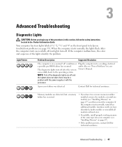
..." in your Owner's Manual. problem with the power supply or with the processor. occurred. If there are no power problems and the system NOTE: If all of the diagnostic If the system does not start, plug the lights turn on and ... operation, all four diagnostic lights stay on and the Unplug the power supply and check the 4-pin power button remains amber, a possible processor power cable connection (see processor power or connection error has "System Board Components" on then does not start, contact Dell for technical off before the computer into a working electrical outlet.
..." in your Owner's Manual. problem with the power supply or with the processor. occurred. If there are no power problems and the system NOTE: If all of the diagnostic If the system does not start, plug the lights turn on and ... operation, all four diagnostic lights stay on and the Unplug the power supply and check the 4-pin power button remains amber, a possible processor power cable connection (see processor power or connection error has "System Board Components" on then does not start, contact Dell for technical off before the computer into a working electrical outlet.
Owner's Manual
Page 66
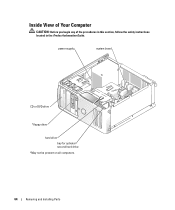
Inside View of Your Computer CAUTION: Before you begin any of the procedures in this section, follow the safety instructions located in the Product Information Guide. power supply system board CD or DVD drive *floppy drive hard drive bay for optional second hard drive *May not be present on all computers. 64 Removing and Installing Parts
Inside View of Your Computer CAUTION: Before you begin any of the procedures in this section, follow the safety instructions located in the Product Information Guide. power supply system board CD or DVD drive *floppy drive hard drive bay for optional second hard drive *May not be present on all computers. 64 Removing and Installing Parts

Owner's Manual
Page 103
...good connection exists between a 10-Mbps network and the computer. The computer is a solid amber light, this indicates a problem with the power supply inside the computer. Connectors External connectors: Video Network adapter USB Audio System board connectors: Primary IDE drive Serial ATA FlexBay Drive Fan PCI ... light) - Activity light (on integrated network yellow blinking light adapter) Diagnostic lights four lights on the front panel (see "Power Problems" on the system board Appendix 101 one frontpanel connector for headphones 40-pin connector on PCI local bus two 7-pin connectors...
...good connection exists between a 10-Mbps network and the computer. The computer is a solid amber light, this indicates a problem with the power supply inside the computer. Connectors External connectors: Video Network adapter USB Audio System board connectors: Primary IDE drive Serial ATA FlexBay Drive Fan PCI ... light) - Activity light (on integrated network yellow blinking light adapter) Diagnostic lights four lights on the front panel (see "Power Problems" on the system board Appendix 101 one frontpanel connector for headphones 40-pin connector on PCI local bus two 7-pin connectors...

Owner's Manual
Page 104
... 230 W Heat dissipation 785 BTU/hr NOTE: Heat dissipation is calculated based upon the power supply wattage rating. Voltage (see the safety instructions manual selection power supply - 90 to 135 V and 180 to 265 V at located in the Product Information 50/60 Hz Guide for important voltage setting information) Backup battery 3-V CR2032 ...
... 230 W Heat dissipation 785 BTU/hr NOTE: Heat dissipation is calculated based upon the power supply wattage rating. Voltage (see the safety instructions manual selection power supply - 90 to 135 V and 180 to 265 V at located in the Product Information 50/60 Hz Guide for important voltage setting information) Backup battery 3-V CR2032 ...

Service Manual
Page 6
... . Close the test screen to return to see if the specific problem is identified. Press the power button, move the mouse, or press a key on the screen. complete. Blinking yellow A power supply or system board failure has occurred. Solid green and a beep code during a test, a message... appears with an error code and a description of the problem you are having. 2. If the computer does not boot, contact Dell for instructions on your hardware ...
... . Close the test screen to return to see if the specific problem is identified. Press the power button, move the mouse, or press a key on the screen. complete. Blinking yellow A power supply or system board failure has occurred. Solid green and a beep code during a test, a message... appears with an error code and a description of the problem you are having. 2. If the computer does not boot, contact Dell for instructions on your hardware ...

Service Manual
Page 7
... computer. l If there is in the Product Information Guide. Solid green power light and no special memory module/memory connector placement requirements exist (see if the specific problem is not identified, contact Dell for technical assistance. Check the diagnostic lights to the system board from a... and the system does not start, there may be a problem with the power supply or with a device (such as the Another failure has occurred. If the problem persists, contact Dell for each card. Also see "Power Problems" in your computer (see "Cards"). 2. Repeat this section, follow ...
... computer. l If there is in the Product Information Guide. Solid green power light and no special memory module/memory connector placement requirements exist (see if the specific problem is not identified, contact Dell for technical assistance. Check the diagnostic lights to the system board from a... and the system does not start, there may be a problem with the power supply or with a device (such as the Another failure has occurred. If the problem persists, contact Dell for each card. Also see "Power Problems" in your computer (see "Cards"). 2. Repeat this section, follow ...

Service Manual
Page 8
... the system does not start, there may be a problem with the power supply or with the processor. Also see "Power Problems" in your Owner's Manual. Unplug the power supply and check the 4-pin processor power cable connection (see "Processor"). on your computer beeps during start , contact Dell for technical assistance. Reseat the processor (see "System Board Components...
... the system does not start, there may be a problem with the power supply or with the processor. Also see "Power Problems" in your Owner's Manual. Unplug the power supply and check the 4-pin processor power cable connection (see "Processor"). on your computer beeps during start , contact Dell for technical assistance. Reseat the processor (see "System Board Components...
Service Manual
Page 14
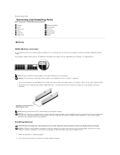
...memory modules in the other connectors. NOTICE: If you remove your computer may have, even if you purchased the new modules from Dell. Installing Memory CAUTION: Before you begin any of your computer's electronic components. You can increase your computer memory by installing an ... warranty. Back to Contents Page Removing and Installing Parts Dell™ Dimension™ 3100/E310 Service Manual Memory Cards Drive Panels Drives Hard Drive Floppy Drive Media Card Reader CD/DVD Drive Processor System Board Power Supply Battery Memory DDR2 Memory Overview If your computer only has...
...memory modules in the other connectors. NOTICE: If you remove your computer may have, even if you purchased the new modules from Dell. Installing Memory CAUTION: Before you begin any of your computer's electronic components. You can increase your computer memory by installing an ... warranty. Back to Contents Page Removing and Installing Parts Dell™ Dimension™ 3100/E310 Service Manual Memory Cards Drive Panels Drives Hard Drive Floppy Drive Media Card Reader CD/DVD Drive Processor System Board Power Supply Battery Memory DDR2 Memory Overview If your computer only has...

Service Manual
Page 37
...all cables to the back of the procedures in this section, follow the safety instructions located in "Before You Begin." 2. Removing the Power Supply 1. Replace the screws attaching the system board. 3. Follow the procedures in the Product Information Guide. Place the system board assembly that attach the... power supply to their connectors at the back of the computer frame. Gently align the board and slide it is identical. Connect your computer...
...all cables to the back of the procedures in this section, follow the safety instructions located in "Before You Begin." 2. Removing the Power Supply 1. Replace the screws attaching the system board. 3. Follow the procedures in the Product Information Guide. Place the system board assembly that attach the... power supply to their connectors at the back of the computer frame. Gently align the board and slide it is identical. Connect your computer...

Service Manual
Page 38
... of the computer frame. 3. Slide the power supply into the computer. 7. Connect the AC power cable to electrical outlets, and turn them over the cables. 6. Replace the computer cover. 1 release button 2 power supply 3 screws (4) 4 AC power connector 5. Lift the power supply up and out of the computer. 6. ...a network cable, first plug the cable into the network wall jack and then plug the cable into place. 2. Replacing the Power Supply CAUTION: Before you begin any of the procedures in this section, follow the safety instructions located in the Product Information Guide. 1....
... of the computer frame. 3. Slide the power supply into the computer. 7. Connect the AC power cable to electrical outlets, and turn them over the cables. 6. Replace the computer cover. 1 release button 2 power supply 3 screws (4) 4 AC power connector 5. Lift the power supply up and out of the computer. 6. ...a network cable, first plug the cable into the network wall jack and then plug the cable into place. 2. Replacing the Power Supply CAUTION: Before you begin any of the procedures in this section, follow the safety instructions located in the Product Information Guide. 1....

Service Manual
Page 41
...amber light - green green light - The computer is calculated based upon the power supply wattage rating. If the system cannot boot and there is a solid amber light, this could indicate a problem with the power supply inside the computer. A good connection exists between a 10-Mbps network and ...Express x1 15-hole connector RJ45 connector two front-panel and four back-panel USB 2.0compliant connectors three connectors for power-on the system board Power DC power supply: Wattage Heat dissipation 230 W 785 BTU/hr NOTE: Heat dissipation is not detecting a physical connection to the network...
...amber light - green green light - The computer is calculated based upon the power supply wattage rating. If the system cannot boot and there is a solid amber light, this could indicate a problem with the power supply inside the computer. A good connection exists between a 10-Mbps network and ...Express x1 15-hole connector RJ45 connector two front-panel and four back-panel USB 2.0compliant connectors three connectors for power-on the system board Power DC power supply: Wattage Heat dissipation 230 W 785 BTU/hr NOTE: Heat dissipation is not detecting a physical connection to the network...

Service Manual
Page 48
Back to Contents Page Technical Overview Dell™ Dimension™ 3100/E310 Service Manual Inside View of Your Computer System Board Components Power Supply DC Connector Pin Assignments Inside View of Your Computer 1 bay for optional second hard drive 2 hard drive 3 floppy drive* 4 CD or DVD drive 5 power supply 6 system board System Board Components
Back to Contents Page Technical Overview Dell™ Dimension™ 3100/E310 Service Manual Inside View of Your Computer System Board Components Power Supply DC Connector Pin Assignments Inside View of Your Computer 1 bay for optional second hard drive 2 hard drive 3 floppy drive* 4 CD or DVD drive 5 power supply 6 system board System Board Components

Service Manual
Page 50
Power Supply DC Connector Pin Assignments DC Power Connector P1 Pin Number 1 2 3 4 5 6 7 8 9 10 11 12 13 14 15 16 17 18 19 20 21 22 Signal Name +3.3 VDC +3.3 VDC COM +5 VDC COM +5 VDC COM POK +5 VFP +12 VB DC +12VB DC +3.3 VDC +3.3 VDC -12 VDC COM PS-ON COM COM COM N/C +5 VDC +5 VDC Color Orange Orange Black Red Black Red Black Gray Purple Yellow Yellow Orange Orange Blue Black Green Black Black Black N/C Red Red Wire Gauge 18-AWG 18-AWG 18-AWG 18-AWG 18-AWG 18-AWG 18-AWG 18-AWG 18-AWG 18-AWG 18-AWG 18-AWG 18-AWG 18-AWG 18-AWG 18-AWG 18-AWG 18-AWG 18-AWG 18-AWG 18-AWG 18-AWG
Power Supply DC Connector Pin Assignments DC Power Connector P1 Pin Number 1 2 3 4 5 6 7 8 9 10 11 12 13 14 15 16 17 18 19 20 21 22 Signal Name +3.3 VDC +3.3 VDC COM +5 VDC COM +5 VDC COM POK +5 VFP +12 VB DC +12VB DC +3.3 VDC +3.3 VDC -12 VDC COM PS-ON COM COM COM N/C +5 VDC +5 VDC Color Orange Orange Black Red Black Red Black Gray Purple Yellow Yellow Orange Orange Blue Black Green Black Black Black N/C Red Red Wire Gauge 18-AWG 18-AWG 18-AWG 18-AWG 18-AWG 18-AWG 18-AWG 18-AWG 18-AWG 18-AWG 18-AWG 18-AWG 18-AWG 18-AWG 18-AWG 18-AWG 18-AWG 18-AWG 18-AWG 18-AWG 18-AWG 18-AWG


