
User Manual
Page 2
TABLE OF CONTENTS FOR YOUR SAFETY 1 SAFETY PRECAUTIONS 2 SPECIAL NOTES ON LCD MONITORS 3 BEFORE YOU OPERATE THE MONITOR 3 FEATURES 3 PACKING LIST 3 INSTALLATION INSTRUCTIONS 4 CONTROLS AND CONNECTORS 5 ADJUSTING THE VIEWING ANGLE 6 OPERATING INSTRUCTIONS 7 GENERAL INSTRUCTIONS 7 HOW TO ADJUST A SETTING 9 ADJUSTING THE PICTURE 10-11 PLUG AND PLAY 12 TECHNICAL SUPPORT(FAQ 13-14 ERROR MESSAGE & POSSIBLE SOLUTION 15 APPENDIX 16 SPECIFICATIONS 16-17 FACTORY PRESET TIMING TABLE 18 CONNECTOR PIN ASSIGNMENT 18
TABLE OF CONTENTS FOR YOUR SAFETY 1 SAFETY PRECAUTIONS 2 SPECIAL NOTES ON LCD MONITORS 3 BEFORE YOU OPERATE THE MONITOR 3 FEATURES 3 PACKING LIST 3 INSTALLATION INSTRUCTIONS 4 CONTROLS AND CONNECTORS 5 ADJUSTING THE VIEWING ANGLE 6 OPERATING INSTRUCTIONS 7 GENERAL INSTRUCTIONS 7 HOW TO ADJUST A SETTING 9 ADJUSTING THE PICTURE 10-11 PLUG AND PLAY 12 TECHNICAL SUPPORT(FAQ 13-14 ERROR MESSAGE & POSSIBLE SOLUTION 15 APPENDIX 16 SPECIFICATIONS 16-17 FACTORY PRESET TIMING TABLE 18 CONNECTOR PIN ASSIGNMENT 18
User Manual
Page 3
... instructions, may cause harmful interference to Part 15 of the FCC Rules. The changes or modifications not expressly approved by one or more of the user to which can radiate radio frequency energy, and if not installed and used in a residential installation. WARNING: To prevent fire or shock hazard, do not expose the monitor to qualified personnel only. 1 This manual...
... instructions, may cause harmful interference to Part 15 of the FCC Rules. The changes or modifications not expressly approved by one or more of the user to which can radiate radio frequency energy, and if not installed and used in a residential installation. WARNING: To prevent fire or shock hazard, do not expose the monitor to qualified personnel only. 1 This manual...

User Manual
Page 4
... voltages and other hazards. Use only a cart or stand recommended by the manufacturer and follow the kit instructions. • Slots and openings in the back and bottom of time. Overloading can expose you mount the monitor on a wall or shelf, use a mounting kit approved by the manufacturer or sold with a third (grounding) pin. opening or removing covers can result in fire or...
... voltages and other hazards. Use only a cart or stand recommended by the manufacturer and follow the kit instructions. • Slots and openings in the back and bottom of time. Overloading can expose you mount the monitor on a wall or shelf, use a mounting kit approved by the manufacturer or sold with a third (grounding) pin. opening or removing covers can result in fire or...
User Manual
Page 5
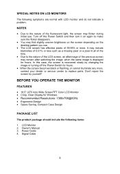
... pixels of the previous screen may remain after switching the image, when the same image is recovered slowly by yourself! Turn off the Power Switch for Windows • Recommended Resolutions: 1366x768@60Hz • Ergonomic Design • Space Saving, Compact Case Design PACKAGE LIST The product package should include the following symptoms are normal with LCD monitor and do not indicate a problem. Owner's Manual 3. Signal Cable 3 SPECIAL NOTES ON LCD MONITORS...
... pixels of the previous screen may remain after switching the image, when the same image is recovered slowly by yourself! Turn off the Power Switch for Windows • Recommended Resolutions: 1366x768@60Hz • Ergonomic Design • Space Saving, Compact Case Design PACKAGE LIST The product package should include the following symptoms are normal with LCD monitor and do not indicate a problem. Owner's Manual 3. Signal Cable 3 SPECIAL NOTES ON LCD MONITORS...

User Manual
Page 6
Make sure that allows operation in your LCD monitor. INSTALLATION INSTRUCTIONS Install Remove Figure 1 Installing and Removing the Base POWER CORD Power Source: 1. Connect the AC-power cord into your LCD monitor's power input socket, The AC-power cord may be connected to either 100/120V AC or 220/240V AC voltage area (No user adjustment is the correct type required in either a wall power outlet or the power outlet socket on your PC, depending on the type of power cord supplied with...
Make sure that allows operation in your LCD monitor. INSTALLATION INSTRUCTIONS Install Remove Figure 1 Installing and Removing the Base POWER CORD Power Source: 1. Connect the AC-power cord into your LCD monitor's power input socket, The AC-power cord may be connected to either 100/120V AC or 220/240V AC voltage area (No user adjustment is the correct type required in either a wall power outlet or the power outlet socket on your PC, depending on the type of power cord supplied with...

User Manual
Page 7
CONTROLS AND CONNECTORS SIGNAL CABLE Connecting the Signal Cable: Plug the Signal Cable one end of the AC power cord to the LCD monitor's AC input socket, and the other end to Wall outlet. Power Cable 2. Signal Cable Caution: If the AC outlet is not grounded (with three holes), install the proper grounding adapter (not supplied). 1 2 Figure 2 Connecting Cables 1. Connecting the Power Cord: Plug one end to LCD monitor's "DSUB-Input" socket , the other end to the computer's VGA port and tighten the two screws on the cable connector.
CONTROLS AND CONNECTORS SIGNAL CABLE Connecting the Signal Cable: Plug the Signal Cable one end of the AC power cord to the LCD monitor's AC input socket, and the other end to Wall outlet. Power Cable 2. Signal Cable Caution: If the AC outlet is not grounded (with three holes), install the proper grounding adapter (not supplied). 1 2 Figure 2 Connecting Cables 1. Connecting the Power Cord: Plug one end to LCD monitor's "DSUB-Input" socket , the other end to the computer's VGA port and tighten the two screws on the cable connector.

User Manual
Page 8
It may cause damage or break the LCD screen. • Careful attention is recommended to look at the full face of the monitor, then adjust the monitor's angle to your fingers or hands when you change the angle. Figure 3 NOTES • Do not touch the LCD screen when you change the monitor's angle. • You are able to adjust the monitor's angle from -5° to 20°. ADJUSTING THE VIEWING ANGLE • For optimal viewing it is required not to catch your own preference. • Hold the stand so you do not topple the monitor when you change the angle. 6
It may cause damage or break the LCD screen. • Careful attention is recommended to look at the full face of the monitor, then adjust the monitor's angle to your fingers or hands when you change the angle. Figure 3 NOTES • Do not touch the LCD screen when you change the monitor's angle. • You are able to adjust the monitor's angle from -5° to 20°. ADJUSTING THE VIEWING ANGLE • For optimal viewing it is required not to catch your own preference. • Hold the stand so you do not topple the monitor when you change the angle. 6
User Manual
Page 9
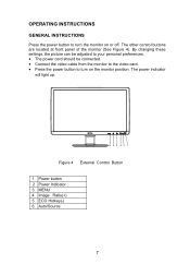
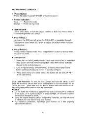
...(-) 6. MENU 4. By changing these settings, the picture can be adjusted to your personal preferences. • The power cord should be connected. • Connect the video cable from the monitor to the video card. • Press the power button to turn on or off. The power indicator will light up. 6 54 32 1 Figure 4 External Control Button 1. Power button 2 Power Indicator 3. Auto/Source 7 Image Ratio(+) 5. The other control buttons are located at front panel of the monitor (See Figure 4). OPERATING INSTRUCTIONS GENERAL INSTRUCTIONS Press the power button...
...(-) 6. MENU 4. By changing these settings, the picture can be adjusted to your personal preferences. • The power cord should be connected. • Connect the video cable from the monitor to the video card. • Press the power button to turn on or off. The power indicator will light up. 6 54 32 1 Figure 4 External Control Button 1. Power button 2 Power Indicator 3. Auto/Source 7 Image Ratio(+) 5. The other control buttons are located at front panel of the monitor (See Figure 4). OPERATING INSTRUCTIONS GENERAL INSTRUCTIONS Press the power button...
User Manual
Page 10
... ever have to change to select the input source showed in the message bar. Orange - OSD Lock Function: To lock the OSD, press and hold the MENU button while the monitor is off , press Auto/Source button continuously to the selected source. 2. Auto configure hot key: When the OSD is activated. • Image Ratio(+) : Select monitor display mode. Power saving mode. • MENU/ENTER : Active OSD menu or function adjust confirm or Exit OSD menu when in Contrast/Brightness OSD status. •...
... ever have to change to select the input source showed in the message bar. Orange - OSD Lock Function: To lock the OSD, press and hold the MENU button while the monitor is off , press Auto/Source button continuously to the selected source. 2. Auto configure hot key: When the OSD is activated. • Image Ratio(+) : Select monitor display mode. Power saving mode. • MENU/ENTER : Active OSD menu or function adjust confirm or Exit OSD menu when in Contrast/Brightness OSD status. •...
User Manual
Page 11
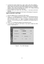
... MENU-button to change the settings of component. Figure 5 The OSD Message 9 Once the desired function is highlighted, press MENU-button to activate it . Press + or - To exit and save, select the exit function. If you want to navigate through the sub-menu functions. If the function selected has a sub-menu, press + or - As a safety precaution, always unplug the monitor before cleaning...
... MENU-button to change the settings of component. Figure 5 The OSD Message 9 Once the desired function is highlighted, press MENU-button to activate it . Press + or - To exit and save, select the exit function. If you want to navigate through the sub-menu functions. If the function selected has a sub-menu, press + or - As a safety precaution, always unplug the monitor before cleaning...

User Manual
Page 12
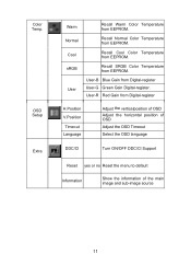
Adjust the horizontal position of the picture. ADJUSTING THE PICTURE The descriptions for function control LEDS Main Menu Item Main Menu Icon Sub Menu Item Sub Menu Description Brightness Backlight Adjustment Contrast Contrast from Digital-register. Image Ratio Enable monitor wide mode or 4:3 mode 10 Adjust Picture Phase to reduce Vertical-Line noise. Standard Standard Mode Text Text Mode Luminance Internet Internet Mode Eco Game Game Mode Movie Movie Mode Sports Sports Mode Image Setup DCR Off Disable dynamic contrast ratio On Enable dynamic contrast ratio ...
Adjust the horizontal position of the picture. ADJUSTING THE PICTURE The descriptions for function control LEDS Main Menu Item Main Menu Icon Sub Menu Item Sub Menu Description Brightness Backlight Adjustment Contrast Contrast from Digital-register. Image Ratio Enable monitor wide mode or 4:3 mode 10 Adjust Picture Phase to reduce Vertical-Line noise. Standard Standard Mode Text Text Mode Luminance Internet Internet Mode Eco Game Game Mode Movie Movie Mode Sports Sports Mode Image Setup DCR Off Disable dynamic contrast ratio On Enable dynamic contrast ratio ...
User Manual
Page 13
... Cool Color Temperature from Digital-register User-G Green Gain Digital-register. OSD Setup Extra Warm Normal Cool sRGB User Recall Warm Color Temperature from Digital-register H.Position V.Position Timeout Language Adjust the verticalposition of OSD Adjust the horizontal position of OSD Adjust the OSD Timeout Select the OSD language DDC/CI Turn ON/OFF DDC/CI Support Reset yes or no Reset the menu to default Information Show the information of the main image and sub-image source 11 Color Temp. User-R Red Gain from...
... Cool Color Temperature from Digital-register User-G Green Gain Digital-register. OSD Setup Extra Warm Normal Cool sRGB User Recall Warm Color Temperature from Digital-register H.Position V.Position Timeout Language Adjust the verticalposition of OSD Adjust the horizontal position of OSD Adjust the OSD Timeout Select the OSD language DDC/CI Turn ON/OFF DDC/CI Support Reset yes or no Reset the menu to default Information Show the information of the main image and sub-image source 11 Color Temp. User-R Red Gain from...
User Manual
Page 14
... data channel based on type connector body, rated 10A, 250V, having standard CEE-22 female configuration. The display is restored by reducing power consumption when there is no video input signal this monitor, following a time-out period, will automatically switch to use a cord set by the Video Electronics Standards Association (VESA) and The Swedish Confederation Employees (NUTEK). USING THE RIGHT POWER CORD : The accessory power cord for the power cord shall be...
... data channel based on type connector body, rated 10A, 250V, having standard CEE-22 female configuration. The display is restored by reducing power consumption when there is no video input signal this monitor, following a time-out period, will automatically switch to use a cord set by the Video Electronics Standards Association (VESA) and The Swedish Confederation Employees (NUTEK). USING THE RIGHT POWER CORD : The accessory power cord for the power cord shall be...
User Manual
Page 15
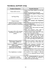
... power LED is ON (orange) but there's no video or no picture. key (AUTO-key). 13 Picture has color defects (white does not look white) Poor brightness or contrast Horizontal or vertical disturbances on the screen Possible Solution *Check if the Power Switch is in the ON position *Power Cord should be connected *Check if the PC system is Plug & Play compatible *Check if the Video Card is Plug & Play compatible *Check if the D-15 plug pin of Video Cable is bent *Adjust the Contrast...
... power LED is ON (orange) but there's no video or no picture. key (AUTO-key). 13 Picture has color defects (white does not look white) Poor brightness or contrast Horizontal or vertical disturbances on the screen Possible Solution *Check if the Power Switch is in the ON position *Power Cord should be connected *Check if the PC system is Plug & Play compatible *Check if the Video Card is Plug & Play compatible *Check if the D-15 plug pin of Video Cable is bent *Adjust the Contrast...
User Manual
Page 16
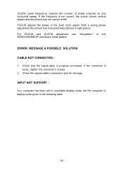
... (pixel frequency) controls the number of the pixel clock signal. Check that the signal-cable is properly connected, If the connector is not correct, the screen shows vertical stripes and the picture has not correct width. For FOCUS and CLOCK adjustment use "dot-pattern" or win 95/98/2000/ME/XP shut-down mode pattern. INPUT NOT SUPPORT : Your computer has been set to unsuitable display mode, set the computer to display mode given in light picture...
... (pixel frequency) controls the number of the pixel clock signal. Check that the signal-cable is properly connected, If the connector is not correct, the screen shows vertical stripes and the picture has not correct width. For FOCUS and CLOCK adjustment use "dot-pattern" or win 95/98/2000/ME/XP shut-down mode pattern. INPUT NOT SUPPORT : Your computer has been set to unsuitable display mode, set the computer to display mode given in light picture...

User Manual
Page 17
Resolution Plug & Play Power Consumption Input Connector Input Video Signal Power Source Environmental Considerations Dimension Weight (N. W.) Driving system TFT Color LCD Size Pixel pitch Video 470 mm(18.5") 0.3mm( H ) ×0.3mm ( V ) R,G,B Analog Interface Separate Sync. APPENDIX SPECIFICATIONS LCD Panel Input Display Colors Dot Clock Max. H/V TTL H-Frequency 31kHz - 83kHz V-Frequency 56-75Hz 16.7M Colors 84.75MHz 1366x768@60Hz VESA DDC2BTM ON Mode OFF Mode ≤25W ≤1W D-Sub 15pin Analog:0.7Vp-p(standard), 75 OHM, Positive 100~240VAC,50/60Hz Operating Temp...
Resolution Plug & Play Power Consumption Input Connector Input Video Signal Power Source Environmental Considerations Dimension Weight (N. W.) Driving system TFT Color LCD Size Pixel pitch Video 470 mm(18.5") 0.3mm( H ) ×0.3mm ( V ) R,G,B Analog Interface Separate Sync. APPENDIX SPECIFICATIONS LCD Panel Input Display Colors Dot Clock Max. H/V TTL H-Frequency 31kHz - 83kHz V-Frequency 56-75Hz 16.7M Colors 84.75MHz 1366x768@60Hz VESA DDC2BTM ON Mode OFF Mode ≤25W ≤1W D-Sub 15pin Analog:0.7Vp-p(standard), 75 OHM, Positive 100~240VAC,50/60Hz Operating Temp...
User Manual
Page 18
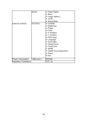
Position • OSD setup • Language • Information • (Warm)Color • (Cool)Color • sRGB • USER Color temperature • Reset • Exit 25Watts FCC, UL 16 Switch External Controls: Functions Power Consumption ( Maximum ) Regulatory Compliance • Power Button • Menu • Image Ratio(+) • ECO/• Source/Auto • Contrast • Brightness • Phase • Clock • H. Position • V.
Position • OSD setup • Language • Information • (Warm)Color • (Cool)Color • sRGB • USER Color temperature • Reset • Exit 25Watts FCC, UL 16 Switch External Controls: Functions Power Consumption ( Maximum ) Regulatory Compliance • Power Button • Menu • Image Ratio(+) • ECO/• Source/Auto • Contrast • Brightness • Phase • Clock • H. Position • V.
User Manual
Page 19
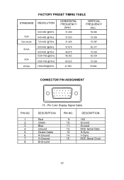
Pin Color Display Signal Cable DESCRIPTION Red Green Blue Ground Detect Cable R-Ground G-Ground B-Ground PIN NO. 9. 10. 11. 12. 13. 14. 15. FACTORY PRESET TIMING TABLE STANDARD RESOLUTION VGA Dos-mode SVGA XGA WXGA 640×480 @60Hz 640×480 @75Hz 720×400 @...HORIZONTAL FREQUENCY (kHz) 31.469 37.500 31.469 37.879 46.875 48.363 60.023 47.852 VERTICAL FREQUENCY (Hz) 59.940 75.000 70.087 60.317 75.000 60.004 75.029 59.964 CONNECTOR PIN ASSIGNMENT 1 5 6 10 11 15 PIN NO. 1. 2. 3. 4. 5. 6. 7. 8. 15 - DESCRIPTION +5V Ground Ground DDC-Serial Data H-Sync V-Sync DDC-Serial...
Pin Color Display Signal Cable DESCRIPTION Red Green Blue Ground Detect Cable R-Ground G-Ground B-Ground PIN NO. 9. 10. 11. 12. 13. 14. 15. FACTORY PRESET TIMING TABLE STANDARD RESOLUTION VGA Dos-mode SVGA XGA WXGA 640×480 @60Hz 640×480 @75Hz 720×400 @...HORIZONTAL FREQUENCY (kHz) 31.469 37.500 31.469 37.879 46.875 48.363 60.023 47.852 VERTICAL FREQUENCY (Hz) 59.940 75.000 70.087 60.317 75.000 60.004 75.029 59.964 CONNECTOR PIN ASSIGNMENT 1 5 6 10 11 15 PIN NO. 1. 2. 3. 4. 5. 6. 7. 8. 15 - DESCRIPTION +5V Ground Ground DDC-Serial Data H-Sync V-Sync DDC-Serial...


