Owner's Manual
Page 19
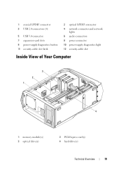
1 coaxial S/PDIF connector 3 USB 2.0 connectors (4) 5 USB 3.0 connector 7 expansion-card slots 9 power-supply diagnostics button 11 security-cable slot latch 2 optical S/PDIF connector 4 network connector and network lights 6 audio connectors 8 power connector 10 power-supply diagnostics light 12 security-cable slot Inside View of Your Computer 3 2 1 4 1 memory module(s) 3 optical drive(s) 2 PCI-Express card(s) 4 hard-drive(s) Technical Overview 19
1 coaxial S/PDIF connector 3 USB 2.0 connectors (4) 5 USB 3.0 connector 7 expansion-card slots 9 power-supply diagnostics button 11 security-cable slot latch 2 optical S/PDIF connector 4 network connector and network lights 6 audio connectors 8 power connector 10 power-supply diagnostics light 12 security-cable slot Inside View of Your Computer 3 2 1 4 1 memory module(s) 3 optical drive(s) 2 PCI-Express card(s) 4 hard-drive(s) Technical Overview 19

Owner's Manual
Page 83
... the tab on page 25. Prerequisites 1 Remove the left side-panel. For additional safety best practices information, see the Regulatory Compliance Homepage at dell.com/regulatory_compliance. Power Supply 83 16 Power-Supply Unit WARNING: Before working inside your computer, read the safety information that shipped with your computer and follow the steps in "Before You...
... the tab on page 25. Prerequisites 1 Remove the left side-panel. For additional safety best practices information, see the Regulatory Compliance Homepage at dell.com/regulatory_compliance. Power Supply 83 16 Power-Supply Unit WARNING: Before working inside your computer, read the safety information that shipped with your computer and follow the steps in "Before You...

Owner's Manual
Page 84
1 2 1 power-supply cover 2 tab 3 Press the securing clips on the DC-wire harness and disconnect the DCwire harness from the power-supply unit. 4 Loosen the captive screws that secure the power-supply unit to the back of the chassis. 5 Slide the power-supply unit out through the back of the chassis. 84 Power Supply
1 2 1 power-supply cover 2 tab 3 Press the securing clips on the DC-wire harness and disconnect the DCwire harness from the power-supply unit. 4 Loosen the captive screws that secure the power-supply unit to the back of the chassis. 5 Slide the power-supply unit out through the back of the chassis. 84 Power Supply

Owner's Manual
Page 85
Power Supply 85 1 2 1 captive screws (4) 2 power-supply unit 6 Remove the screws that secure the power-supply unit to the bezel. 7 Remove the bezel from the power-supply unit.
Power Supply 85 1 2 1 captive screws (4) 2 power-supply unit 6 Remove the screws that secure the power-supply unit to the bezel. 7 Remove the bezel from the power-supply unit.

Owner's Manual
Page 86
...power-supply unit Replacing the Power-Supply Unit 1 Align the screw holes on the power-supply unit with the screw holes on the bezel. 2 Replace the screws that secure the power-supply unit to the bezel. 3 Slide the power-supply unit into the chassis through the back of the computer. 4 Tighten the captive screws that secure the power-supply... unit to the back of the chassis. 5 Connect the DC-wire harness to the power-supply unit. 6 Align the notch on the power-supply cover with the tab on the chassis. 7 Slide the power-supply cover towards the tabs ...
...power-supply unit Replacing the Power-Supply Unit 1 Align the screw holes on the power-supply unit with the screw holes on the bezel. 2 Replace the screws that secure the power-supply unit to the bezel. 3 Slide the power-supply unit into the chassis through the back of the computer. 4 Tighten the captive screws that secure the power-supply... unit to the back of the chassis. 5 Connect the DC-wire harness to the power-supply unit. 6 Align the notch on the power-supply cover with the tab on the chassis. 7 Slide the power-supply cover towards the tabs ...

Owner's Manual
Page 87
Postrequisites 1 Replace the left side-panel. Power Supply 87 See "Replacing the Left Side-Panel" on page 27. 2 Follow the steps in "After Working Inside Your Computer" on page 15.
Postrequisites 1 Replace the left side-panel. Power Supply 87 See "Replacing the Left Side-Panel" on page 27. 2 Follow the steps in "After Working Inside Your Computer" on page 15.

Owner's Manual
Page 121
... 1 Remove the screws that shipped with your computer, read the safety information that secure the right-side bottom panel to the chassis. See "Removing the Power-Supply Unit" on page 121. 7 Remove the right lighting-board. See "Removing the Right-Side Bottom Panel" on page 83. 6 Remove the right-side top ... in "Before You Begin" on page 45. 3 Remove the drive-bay shroud. For additional safety best practices information, see the Regulatory Compliance Homepage at dell.com/regulatory_compliance. See "Removing the Right Lighting- See "Removing the Drive-Bay Shroud" on page 15."
... 1 Remove the screws that shipped with your computer, read the safety information that secure the right-side bottom panel to the chassis. See "Removing the Power-Supply Unit" on page 121. 7 Remove the right lighting-board. See "Removing the Right-Side Bottom Panel" on page 83. 6 Remove the right-side top ... in "Before You Begin" on page 45. 3 Remove the drive-bay shroud. For additional safety best practices information, see the Regulatory Compliance Homepage at dell.com/regulatory_compliance. See "Removing the Right Lighting- See "Removing the Drive-Bay Shroud" on page 15."

Owner's Manual
Page 124
.... 8 Replace the left side-panel. See "Closing the PCI Shroud" on page 110. 4 Replace the power-supply unit. See "Replacing the Right Lighting-Board" on page 86. 5 Replace the hard-drive fan assembly. See "Replacing the Power-Supply Unit" on page 118. 3 Replace the right-side top panel. See "Replacing the Hard-Drive Fan...
.... 8 Replace the left side-panel. See "Closing the PCI Shroud" on page 110. 4 Replace the power-supply unit. See "Replacing the Right Lighting-Board" on page 86. 5 Replace the hard-drive fan assembly. See "Replacing the Power-Supply Unit" on page 118. 3 Replace the right-side top panel. See "Replacing the Hard-Drive Fan...

Owner's Manual
Page 133
... additional safety best practices information, see the Regulatory Compliance Homepage at dell.com/regulatory_compliance. See "Removing the Left Side-Panel" on page 83. 3 Remove the processor liquid-cooling assembly. Back Bezel 133 See "Removing the Power-Supply Unit" on page 25. 2 Remove the power-supply unit. See "Removing the Processor Liquid-Cooling Assembly" on page...
... additional safety best practices information, see the Regulatory Compliance Homepage at dell.com/regulatory_compliance. See "Removing the Left Side-Panel" on page 83. 3 Remove the processor liquid-cooling assembly. Back Bezel 133 See "Removing the Power-Supply Unit" on page 25. 2 Remove the power-supply unit. See "Removing the Processor Liquid-Cooling Assembly" on page...

Owner's Manual
Page 136
... processor liquid-cooling assembly. Replacing the Back Bezel 1 Align the tabs on the back bezel with the slots on page 72. 2 Replace the power-supply unit. See "Replacing the Power-Supply Unit" on page 15. 136 Back Bezel See "Replacing the Left Side-Panel" on page 27. 4 Follow the steps in "After Working Inside...
... processor liquid-cooling assembly. Replacing the Back Bezel 1 Align the tabs on the back bezel with the slots on page 72. 2 Replace the power-supply unit. See "Replacing the Power-Supply Unit" on page 15. 136 Back Bezel See "Replacing the Left Side-Panel" on page 27. 4 Follow the steps in "After Working Inside...


