
Owner's Manual
Page 4
5 Hard Drive(s 29 Prerequisites 29 Removing the Hard Drive(s 29 Replacing the Hard Drive(s 30 Postrequisites 30 6 Hard-Drive Fan Assembly 33 Prerequisites 33 Removing the Hard-Drive Fan Assembly 33 Replacing the Hard-Drive Fan Assembly 34 Postrequisites 35 7 Optical Drive(s 37 Prerequisites 37 Removing the Optical Drive(s 37 Replacing the Optical Drive(s 38 Postrequisites 38 8 Media-Card Reader 41 Prerequisites 41 Removing the Media-Card Reader 41 Replacing the Media-Card Reader 43 4 Contents
5 Hard Drive(s 29 Prerequisites 29 Removing the Hard Drive(s 29 Replacing the Hard Drive(s 30 Postrequisites 30 6 Hard-Drive Fan Assembly 33 Prerequisites 33 Removing the Hard-Drive Fan Assembly 33 Replacing the Hard-Drive Fan Assembly 34 Postrequisites 35 7 Optical Drive(s 37 Prerequisites 37 Removing the Optical Drive(s 37 Replacing the Optical Drive(s 38 Postrequisites 38 8 Media-Card Reader 41 Prerequisites 41 Removing the Media-Card Reader 41 Replacing the Media-Card Reader 43 4 Contents
Owner's Manual
Page 13
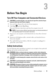
... the power source. NOTE: If you finish working inside the computer, replace all covers, panels, and screws before connecting to ground the system board. After you are using a different operating system, see the Regulatory Compliance Homepage at dell.com/regulatory_compliance. For additional safety best practices information, see the documentation of your operating system for shut-down and then the computer turns off your...
... the power source. NOTE: If you finish working inside the computer, replace all covers, panels, and screws before connecting to ground the system board. After you are using a different operating system, see the Regulatory Compliance Homepage at dell.com/regulatory_compliance. For additional safety best practices information, see the documentation of your operating system for shut-down and then the computer turns off your...
Owner's Manual
Page 14
... nut driver • Flash BIOS executable update program available at the back of the components inside your computer, ground yourself by touching an unpainted metal surface, such as the metal at support.dell.com 14 Before you disconnect a cable, pull on its connector or on its pull-tab, not on the cable itself. CAUTION: When you Begin CAUTION: To disconnect a network cable...
... nut driver • Flash BIOS executable update program available at the back of the components inside your computer, ground yourself by touching an unpainted metal surface, such as the metal at support.dell.com 14 Before you disconnect a cable, pull on its connector or on its pull-tab, not on the cable itself. CAUTION: When you Begin CAUTION: To disconnect a network cable...
Owner's Manual
Page 15
.... After Working Inside Your Computer 15 4 After Working Inside Your Computer After you complete replacement procedures, ensure the following: • Replace all screws and ensure no stray screws remain inside your computer • Connect any external devices, cables, cards, and any other part you removed before working on your computer • Connect your computer and all attached devices to do so may damage your computer. • Turn on...
.... After Working Inside Your Computer 15 4 After Working Inside Your Computer After you complete replacement procedures, ensure the following: • Replace all screws and ensure no stray screws remain inside your computer • Connect any external devices, cables, cards, and any other part you removed before working on your computer • Connect your computer and all attached devices to do so may damage your computer. • Turn on...
Owner's Manual
Page 19
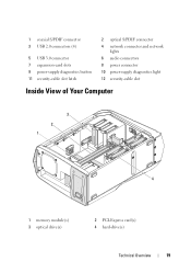
1 coaxial S/PDIF connector 3 USB 2.0 connectors (4) 5 USB 3.0 connector 7 expansion-card slots 9 power-supply diagnostics button 11 security-cable slot latch 2 optical S/PDIF connector 4 network connector and network lights 6 audio connectors 8 power connector 10 power-supply diagnostics light 12 security-cable slot Inside View of Your Computer 3 2 1 4 1 memory module(s) 3 optical drive(s) 2 PCI-Express card(s) 4 hard-drive(s) Technical Overview 19
1 coaxial S/PDIF connector 3 USB 2.0 connectors (4) 5 USB 3.0 connector 7 expansion-card slots 9 power-supply diagnostics button 11 security-cable slot latch 2 optical S/PDIF connector 4 network connector and network lights 6 audio connectors 8 power connector 10 power-supply diagnostics light 12 security-cable slot Inside View of Your Computer 3 2 1 4 1 memory module(s) 3 optical drive(s) 2 PCI-Express card(s) 4 hard-drive(s) Technical Overview 19

Owner's Manual
Page 23
9 hard-drive LED connector (HDD_LED1) 10 hard-drive LED connector (HDD_LED2) 11 USB connector (MB_USB) 12 main-power connector (PWR1) 13 system-board lighting (MB_MIO) 14 hard-drive fan connector (FAN_HDD) 15 right side-panel connector (SIDE_R) 16 ODD sensors (ODD_SW) 17 ODD LED connector (ODD_LED) 18 front-default connector (FACTORY_DEFAULT) 19 Debug connector (DEBUG) 20 graphics-temperature sensor connector (GFX_TEMP) 21 graphics-pump connector (GFX_PUMP) Top Lighting-Board Components 1 23 45 1 System fan connector (SYS FAN) 2 CPU fan connector (CPU FAN) 3 Temperature sensor ...
9 hard-drive LED connector (HDD_LED1) 10 hard-drive LED connector (HDD_LED2) 11 USB connector (MB_USB) 12 main-power connector (PWR1) 13 system-board lighting (MB_MIO) 14 hard-drive fan connector (FAN_HDD) 15 right side-panel connector (SIDE_R) 16 ODD sensors (ODD_SW) 17 ODD LED connector (ODD_LED) 18 front-default connector (FACTORY_DEFAULT) 19 Debug connector (DEBUG) 20 graphics-temperature sensor connector (GFX_TEMP) 21 graphics-pump connector (GFX_PUMP) Top Lighting-Board Components 1 23 45 1 System fan connector (SYS FAN) 2 CPU fan connector (CPU FAN) 3 Temperature sensor ...

Owner's Manual
Page 34
1 2 1 hard-drive fan cable 2 hard-drive fan assembly Replacing the Hard-Drive Fan Assembly 1 Slide the hard-drive fan assembly into the hard-drive fan assembly bay. 2 Route the cable through the slot in the hard-drive bay and then connect the hard-drive fan assembly cable to the FAN_HDD connector on page 48. 4 Close the PCI shroud. See "Replacing the Drive-Bay Shroud" on the master I/O board. 3 Replace the drive-bay shroud. See "Closing the PCI Shroud" on page 46. 34 Hard-Drive Fan Assembly
1 2 1 hard-drive fan cable 2 hard-drive fan assembly Replacing the Hard-Drive Fan Assembly 1 Slide the hard-drive fan assembly into the hard-drive fan assembly bay. 2 Route the cable through the slot in the hard-drive bay and then connect the hard-drive fan assembly cable to the FAN_HDD connector on page 48. 4 Close the PCI shroud. See "Replacing the Drive-Bay Shroud" on the master I/O board. 3 Replace the drive-bay shroud. See "Closing the PCI Shroud" on page 46. 34 Hard-Drive Fan Assembly
Owner's Manual
Page 97
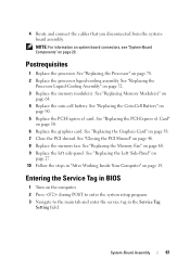
... 46. 8 Replace the memory fan. See "Closing the PCI Shroud" on page 50. 6 Replace the graphics card. Postrequisites 1 Replace the processor. See "Replacing Memory Module(s)" on page 68. 9 Replace the left side-panel. See "Replacing the Memory Fan" on page 64. 4 Replace the coin-cell battery. Entering the Service Tag in BIOS 1 Turn on page 78. 2 Replace the processor liquid-cooling assembly. See "Replacing the Processor" on the computer. 2 Press during POST to enter the system setup program...
... 46. 8 Replace the memory fan. See "Closing the PCI Shroud" on page 50. 6 Replace the graphics card. Postrequisites 1 Replace the processor. See "Replacing Memory Module(s)" on page 68. 9 Replace the left side-panel. See "Replacing the Memory Fan" on page 64. 4 Replace the coin-cell battery. Entering the Service Tag in BIOS 1 Turn on page 78. 2 Replace the processor liquid-cooling assembly. See "Replacing the Processor" on the computer. 2 Press during POST to enter the system setup program...

Owner's Manual
Page 99
... 47. 4 Remove the PCI-fan. Master I /O board. Prerequisites 1 Remove the left side-panel. See "Removing the Drive-Bay Shroud" on page 25. 2 Open the PCI shroud. See "Removing the PCI-Fan" on page 45. 3 Remove the drive-bay shroud. NOTE: Note the routing of the chassis. For additional safety best practices information, see the Regulatory Compliance Homepage at dell.com/regulatory_compliance. 20 Master I/O Board WARNING: Before working inside your...
... 47. 4 Remove the PCI-fan. Master I /O board. Prerequisites 1 Remove the left side-panel. See "Removing the Drive-Bay Shroud" on page 25. 2 Open the PCI shroud. See "Removing the PCI-Fan" on page 45. 3 Remove the drive-bay shroud. NOTE: Note the routing of the chassis. For additional safety best practices information, see the Regulatory Compliance Homepage at dell.com/regulatory_compliance. 20 Master I/O Board WARNING: Before working inside your...

Owner's Manual
Page 103
...: Before working inside your computer, read the safety information that shipped with your computer and follow the steps in "Before You Begin" on page 25. 2 Remove the optical drive(s). See "Removing the Optical Drive(s)" on the top lighting-board. 2 Remove the screws that you can reconnect them correctly after you replace the top lighting-board. 1 Disconnect all cables from the top lighting-board, note the location of the connectors...
...: Before working inside your computer, read the safety information that shipped with your computer and follow the steps in "Before You Begin" on page 25. 2 Remove the optical drive(s). See "Removing the Optical Drive(s)" on the top lighting-board. 2 Remove the screws that you can reconnect them correctly after you replace the top lighting-board. 1 Disconnect all cables from the top lighting-board, note the location of the connectors...

Owner's Manual
Page 117
See "Removing the Right Lighting- Prerequisites 1 Remove the left side-panel. Removing the Right Lighting-Board 1 Disconnect the right lighting-board cable from the SIDE_R connector on the master I/O board. 2 Note the right lighting-board cable routing and remove it from the slot on page 13. Right Lighting-Board 117 24 Right Lighting-Board WARNING: Before working inside your computer, read the safety information that shipped with your computer and follow the steps in...
See "Removing the Right Lighting- Prerequisites 1 Remove the left side-panel. Removing the Right Lighting-Board 1 Disconnect the right lighting-board cable from the SIDE_R connector on the master I/O board. 2 Note the right lighting-board cable routing and remove it from the slot on page 13. Right Lighting-Board 117 24 Right Lighting-Board WARNING: Before working inside your computer, read the safety information that shipped with your computer and follow the steps in...

Owner's Manual
Page 121
... Right-Side Middle Panel" on page 69. 5 Remove the power-supply unit. Prerequisites 1 Remove the left side-panel. on page 113. Board" on page 25. 2 Open the PCI shroud. See "Removing the Left Side-Panel" on page 117. 8 Remove the right-side middle panel. See "Removing the Right-Side Bottom Panel" on page 47. 4 Remove the hard-drive fan assembly. 25 Right-Side Bottom Panel WARNING: Before working inside your computer, read...
... Right-Side Middle Panel" on page 69. 5 Remove the power-supply unit. Prerequisites 1 Remove the left side-panel. on page 113. Board" on page 25. 2 Open the PCI shroud. See "Removing the Left Side-Panel" on page 117. 8 Remove the right-side middle panel. See "Removing the Right-Side Bottom Panel" on page 47. 4 Remove the hard-drive fan assembly. 25 Right-Side Bottom Panel WARNING: Before working inside your computer, read...

Owner's Manual
Page 128
... "Replacing the Drive-Bay Shroud" on page 96. 3 Replace the top lighting-board. 3 Align the top panel with the slots in "After Working Inside Your Computer" on page 110. 2 Replace the system board. See "Replacing the System-Board Assembly" on page 48. 5 Close the PCI shroud. See "Replacing the Top Lighting-Board" on page 46. 6 Replace the memory fan. See "Closing the PCI Shroud" on page 104. 4 Replace the drive-bay shroud. See "Replacing...
... "Replacing the Drive-Bay Shroud" on page 96. 3 Replace the top lighting-board. 3 Align the top panel with the slots in "After Working Inside Your Computer" on page 110. 2 Replace the system board. See "Replacing the System-Board Assembly" on page 48. 5 Close the PCI shroud. See "Replacing the Top Lighting-Board" on page 46. 6 Replace the memory fan. See "Closing the PCI Shroud" on page 104. 4 Replace the drive-bay shroud. See "Replacing...
Owner's Manual
Page 145
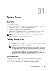
... areas: the setup item, active help screen, and key functions. If you change a user-selectable option, such as the user password, type of the hard drive, and so on • change the system configuration information • set or change system setup, it , and then press . This prompt can appear very quickly, so you see the Microsoft Windows desktop. If you wait too long and the operating system logo appears...
... areas: the setup item, active help screen, and key functions. If you change a user-selectable option, such as the user password, type of the hard drive, and so on • change the system configuration information • set or change system setup, it , and then press . This prompt can appear very quickly, so you see the Microsoft Windows desktop. If you wait too long and the operating system logo appears...

Owner's Manual
Page 147
... processor speed. Displays the processor L3 cache size. Displays the SATA 1 drive integrated in the computer. Displays the processor L2 cache size. System Setup Utility 147 Advanced BIOS Features Bootup Num-Lock Displays the type of memory technology used. Displays the SATA 6 drive integrated in the computer. If enabled, the system will HALT during boot to display system errors. Displays the SATA 4 drive integrated in the computer. Displays the memory speed. Displays the SATA 5 drive integrated in the computer. Memory Technology Memory Speed CPU Information Processor ID CPU...
... processor speed. Displays the processor L3 cache size. Displays the SATA 1 drive integrated in the computer. Displays the processor L2 cache size. System Setup Utility 147 Advanced BIOS Features Bootup Num-Lock Displays the type of memory technology used. Displays the SATA 6 drive integrated in the computer. If enabled, the system will HALT during boot to display system errors. Displays the SATA 4 drive integrated in the computer. Displays the memory speed. Displays the SATA 5 drive integrated in the computer. Memory Technology Memory Speed CPU Information Processor ID CPU...
Owner's Manual
Page 148
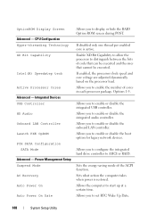
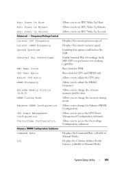
Power Management Setup Suspend Mode AC Recovery Auto Power On Auto Power On Date Allows you to display or hide the RAID Option ROM screen during POST. Allows you to set RTC Wake Up Date. 148 System Setup Utility If disabled only one thread per enabled core is restored. Allows you to enable the number of cores in each processor package. Options 1-5. Allows you to enable or disable the boot option for legacy network devices. Sets the energy-saving mode of code that...
Power Management Setup Suspend Mode AC Recovery Auto Power On Auto Power On Date Allows you to display or hide the RAID Option ROM screen during POST. Allows you to set RTC Wake Up Date. 148 System Setup Utility If disabled only one thread per enabled core is restored. Allows you to enable the number of cores in each processor package. Options 1-5. Allows you to enable or disable the boot option for legacy network devices. Sets the energy-saving mode of code that...
Owner's Manual
Page 149
... to access the Overvoltage Configuration submenu. Allows you to set RTC Wake Up Hour. Allows you to adjust the CPU ratio. Enabling this option could reduce the EMI. Allows you to change the memory timing mode. Base clock for DMI Base clock for KSKU CPUs to change the Advance DRAM Configuration. Displays the Command Rate (editable in Manual Mode). Displays the current memory speed. Enable Internal PLL Overvoltage for CPU and...
... to access the Overvoltage Configuration submenu. Allows you to set RTC Wake Up Hour. Allows you to adjust the CPU ratio. Enabling this option could reduce the EMI. Allows you to change the memory timing mode. Base clock for DMI Base clock for KSKU CPUs to change the Advance DRAM Configuration. Displays the Command Rate (editable in Manual Mode). Displays the current memory speed. Enable Internal PLL Overvoltage for CPU and...
Owner's Manual
Page 152
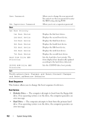
... items displayed are dynamically updated according to boot from the primary hard drive. Boot Options • Diskette Drive - The computer attempts to the hard drives detected. The computer attempts to enter the BIOS setup, during POST. You cannot use the user password to boot from the floppy disk drive. Allows you to change the user password. Exit Provides options to set a supervisor password. If no operating system is on the drive, the computer generates an error message. • Hard Drive - Hard Disk Drive...
... items displayed are dynamically updated according to boot from the primary hard drive. Boot Options • Diskette Drive - The computer attempts to the hard drives detected. The computer attempts to enter the BIOS setup, during POST. You cannot use the user password to boot from the floppy disk drive. Allows you to change the user password. Exit Provides options to set a supervisor password. If no operating system is on the drive, the computer generates an error message. • Hard Drive - Hard Disk Drive...

Owner's Manual
Page 153
... boot from the optical drive to a USB memory key, highlight USB Storage Device and press . See "Entering System Setup" on (or restart) your computer and try again. When F12 Boot Options appears in the lower-right corner of the screen, press . The BIOS detects the device and adds the USB flash option to boot from the network. The Boot Device Menu appears, listing all available boot devices. 4 On the Boot Device Menu choose the device you see the Microsoft Windows desktop. If no operating...
... boot from the optical drive to a USB memory key, highlight USB Storage Device and press . See "Entering System Setup" on (or restart) your computer and try again. When F12 Boot Options appears in the lower-right corner of the screen, press . The BIOS detects the device and adds the USB flash option to boot from the network. The Boot Device Menu appears, listing all available boot devices. 4 On the Boot Device Menu choose the device you see the Microsoft Windows desktop. If no operating...

Owner's Manual
Page 154
... 3-pin password reset jumper (PASSWORD_CLEAR) on page 13. NOTE: Write down -arrow keys to move through the list of devices. 4 Press plus (+) or minus (-) to clear the CMOS setting. 1 Remove the left side-panel. See "System-Board Components" on page 20. 3 Remove the 2-pin jumper plug from the electrical outlet to change the boot priority of the device. and down your computer and follow the steps in case you want to restore...
... 3-pin password reset jumper (PASSWORD_CLEAR) on page 13. NOTE: Write down -arrow keys to move through the list of devices. 4 Press plus (+) or minus (-) to clear the CMOS setting. 1 Remove the left side-panel. See "System-Board Components" on page 20. 3 Remove the 2-pin jumper plug from the electrical outlet to change the boot priority of the device. and down your computer and follow the steps in case you want to restore...


