Desktop Manual
Page 3
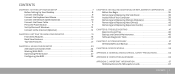
... Desktop 8 Connect the Display 9 Connect the Keyboard and Mouse 10 Connect the Network Cable (Optional 10 Connect the Power Cable 11 Press the Power Button 11 Set Up Microsoft Windows 12 Connect to the Internet (Optional 12 CHAPTER 2: GETTING TO KNOW YOUR DESKTOP 15 Front View Features 16 Back View Features 17 Top View Features 21 CHAPTER 4: USING YOUR DESKTOP 23 Alienware Command Center 24 Working With RAID 24 Optimizing Performance 27 Configuring the BIOS 28 CHAPTER 5: INSTALLING ADDITIONAL OR REPLACEMENT...
... Desktop 8 Connect the Display 9 Connect the Keyboard and Mouse 10 Connect the Network Cable (Optional 10 Connect the Power Cable 11 Press the Power Button 11 Set Up Microsoft Windows 12 Connect to the Internet (Optional 12 CHAPTER 2: GETTING TO KNOW YOUR DESKTOP 15 Front View Features 16 Back View Features 17 Top View Features 21 CHAPTER 4: USING YOUR DESKTOP 23 Alienware Command Center 24 Working With RAID 24 Optimizing Performance 27 Configuring the BIOS 28 CHAPTER 5: INSTALLING ADDITIONAL OR REPLACEMENT...

Desktop Manual
Page 8
..., be needed to many of receiving a shipment will not be easily accessed. 8 CHAPTER 1: SETTING UP YOUR DESKTOP Placing Your Desktop WARNING: Do not place the desktop near or over a radiator or heating vent. Begin by carefully opening the box and removing all or parts of , behind, or below the desktop. • The desktop has enough room so that optical drives and other cable connectors are...
..., be needed to many of receiving a shipment will not be easily accessed. 8 CHAPTER 1: SETTING UP YOUR DESKTOP Placing Your Desktop WARNING: Do not place the desktop near or over a radiator or heating vent. Begin by carefully opening the box and removing all or parts of , behind, or below the desktop. • The desktop has enough room so that optical drives and other cable connectors are...

Desktop Manual
Page 12
... instructions in "Setting Up Your Internet Connection" on the screen. Before you can use your wireless Internet connection, you download and install the latest BIOS and drivers for setup instructions. Follow the instructions on the operating system and features, see the documentation that shipped with the operating system settings that you need to connect to the telephone wall jack before you set up connection, connect the telephone line to the external USB modem (optional) and to your wired Internet connection...
... instructions in "Setting Up Your Internet Connection" on the screen. Before you can use your wireless Internet connection, you download and install the latest BIOS and drivers for setup instructions. Follow the instructions on the operating system and features, see the documentation that shipped with the operating system settings that you need to connect to the telephone wall jack before you set up connection, connect the telephone line to the external USB modem (optional) and to your wired Internet connection...

Desktop Manual
Page 19
...Aurora ALX only). Connects to high-speed serial multimedia devices such as a mouse, keyboard, printer, external drive, or MP3 player. 4 Audio connectors - Connect to USB devices, such as digital video cameras. 7 Coaxial S/PDIF connector - Connect to eSATA compatible storage devices such as external hard drives or optical drives. 3 USB 2.0 connectors (6) - Back Panel Connectors 1 7 6 2 3 5 4 NOTE: Some back panel connectors may not be available on your computer to a network or broadband device. 6 IEEE 1394 connector - For details, see "Connecting External Speakers...
...Aurora ALX only). Connects to high-speed serial multimedia devices such as a mouse, keyboard, printer, external drive, or MP3 player. 4 Audio connectors - Connect to USB devices, such as digital video cameras. 7 Coaxial S/PDIF connector - Connect to eSATA compatible storage devices such as external hard drives or optical drives. 3 USB 2.0 connectors (6) - Back Panel Connectors 1 7 6 2 3 5 4 NOTE: Some back panel connectors may not be available on your computer to a network or broadband device. 6 IEEE 1394 connector - For details, see "Connecting External Speakers...
Desktop Manual
Page 28
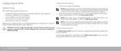
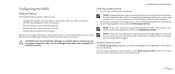
Turn on the keyboard is held down for your desktop. System Setup Screens The BIOS Setup Utility displays current or changeable configuration information for extended periods of time. Key functions appear at the bottom of hard drive installed. CAUTION: Do not change a user-selectable option. • View the amount of memory installed. • Set the type of the BIOS Setup Utility screen and lists keys and their functions within the active field. 28 CHAPTER 4: USING YOUR DESKTOP NOTE: Keyboard failure may result...
Turn on the keyboard is held down for your desktop. System Setup Screens The BIOS Setup Utility displays current or changeable configuration information for extended periods of time. Key functions appear at the bottom of hard drive installed. CAUTION: Do not change a user-selectable option. • View the amount of memory installed. • Set the type of the BIOS Setup Utility screen and lists keys and their functions within the active field. 28 CHAPTER 4: USING YOUR DESKTOP NOTE: Keyboard failure may result...

Desktop Manual
Page 29
... model and installed devices. CHAPTER 4: USING YOUR DESKTOP 29 Displays the memory speed. Displays the asset tag of the computer. Displays the processor L3 cache size. Standard CMOS Features System Time (hh:mm:ss) System Date (mm:dd:yy) SATA 1 SATA 2 SATA 3 SATA 4 SATA 5 SATA 6 Displays the current time. System Setup Options NOTE: The items listed in this section may or may not appear exactly as listed depending on Aurora and Aurora ALX only) Displays the QPI speed. Displays...
... model and installed devices. CHAPTER 4: USING YOUR DESKTOP 29 Displays the memory speed. Displays the asset tag of the computer. Displays the processor L3 cache size. Standard CMOS Features System Time (hh:mm:ss) System Date (mm:dd:yy) SATA 1 SATA 2 SATA 3 SATA 4 SATA 5 SATA 6 Displays the current time. System Setup Options NOTE: The items listed in this section may or may not appear exactly as listed depending on Aurora and Aurora ALX only) Displays the QPI speed. Displays...

Desktop Manual
Page 31
... integrated hard drive controller to AHCI or RAID. Allows you to enable and disable the network controller's boot option. CHAPTER 4: USING YOUR DESKTOP 31 Allows you to enable or disable the onboard IEEE 1394 controller. Sets the system to start up from an onboard LAN, PCIE-X1 LAN card, or a PCI LAN card. Allows you to enable or disable the onboard LAN controller. Allows the computer to wake up at a certain time. Power Management Setup Suspend Mode AC Recovery Remote Wakeup (available on Aurora and Aurora ALX...
... integrated hard drive controller to AHCI or RAID. Allows you to enable and disable the network controller's boot option. CHAPTER 4: USING YOUR DESKTOP 31 Allows you to enable or disable the onboard IEEE 1394 controller. Sets the system to start up from an onboard LAN, PCIE-X1 LAN card, or a PCI LAN card. Allows you to enable or disable the onboard LAN controller. Allows the computer to wake up at a certain time. Power Management Setup Suspend Mode AC Recovery Remote Wakeup (available on Aurora and Aurora ALX...

Desktop Manual
Page 37
... safety. CAUTION: Only a certified service technician should perform repairs on the cable itself. Damage due to ensure your desktop and all telephone or network cables from your desktop (see the Regulatory Compliance Homepage at www.dell.com/ regulatory_compliance. Turn off your desktop and then unplug the cable from being scratched. 2. CHAPTER 5: INSTALLING ADDITIONAL OR REPLACEMENT COMPONENTS 37 Hold a card by its pull-tab, not...
... safety. CAUTION: Only a certified service technician should perform repairs on the cable itself. Damage due to ensure your desktop and all telephone or network cables from your desktop (see the Regulatory Compliance Homepage at www.dell.com/ regulatory_compliance. Turn off your desktop and then unplug the cable from being scratched. 2. CHAPTER 5: INSTALLING ADDITIONAL OR REPLACEMENT COMPONENTS 37 Hold a card by its pull-tab, not...

Desktop Manual
Page 38
... cable from your desktop. NOTE: Theater lighting (available only on Alienware Aurora ALX) turns on page 36. Slide the latch to the right to open the side panel. 4. Theater lighting is removed. To remove the side panel: 1. Place the side panel in "Before You Begin" on automatically when the side panel is powered by internal batteries. Lift the release panel to unlock the release panel. 3. Follow the instructions in a secure location. To replace...
... cable from your desktop. NOTE: Theater lighting (available only on Alienware Aurora ALX) turns on page 36. Slide the latch to the right to open the side panel. 4. Theater lighting is removed. To remove the side panel: 1. Place the side panel in "Before You Begin" on automatically when the side panel is powered by internal batteries. Lift the release panel to unlock the release panel. 3. Follow the instructions in a secure location. To replace...

Desktop Manual
Page 39
... both ends of Your Computer 3 2 1 1 memory module(s) 3 optical drives (3) 2 graphics cards (2) 4 hard drives (4) Removing and Replacing Memory Module(s) To remove the memory module(s): 1. CHAPTER 5: INSTALLING ADDITIONAL OR REPLACEMENT COMPONENTS 39 Inside View of the memory module connector. 5. Remove the side panel (see "Inside View of Your Computer" on page 38). 3. Locate the memory module connectors on the system board (see "Removing and Replacing the Side Panel" on page 39). Follow the instructions in "Before You Begin" on page...
... both ends of Your Computer 3 2 1 1 memory module(s) 3 optical drives (3) 2 graphics cards (2) 4 hard drives (4) Removing and Replacing Memory Module(s) To remove the memory module(s): 1. CHAPTER 5: INSTALLING ADDITIONAL OR REPLACEMENT COMPONENTS 39 Inside View of the memory module connector. 5. Remove the side panel (see "Inside View of Your Computer" on page 38). 3. Locate the memory module connectors on the system board (see "Removing and Replacing the Side Panel" on page 39). Follow the instructions in "Before You Begin" on page...

Desktop Manual
Page 41
... on the memory module connector. 4 3 2 1 3. Replace the side panel (see "Removing and Replacing the Side Panel" on the computer. 1. As the computer boots, it detects the additional memory and automatically updates the system configuration information. Insert the memory module into the memory module connector until the memory module snaps into the cutouts at each end of memory installed in "Before You Begin" on page 36. 2. Turn on page...
... on the memory module connector. 4 3 2 1 3. Replace the side panel (see "Removing and Replacing the Side Panel" on the computer. 1. As the computer boots, it detects the additional memory and automatically updates the system configuration information. Insert the memory module into the memory module connector until the memory module snaps into the cutouts at each end of memory installed in "Before You Begin" on page 36. 2. Turn on page...

Desktop Manual
Page 42
Follow the instructions in "Before You Begin" on page 38). 3. Disconnect the power and data cable from the hard drive (if applicable). 1 2 4. Remove the side panel (see "Removing and Replacing the Side Panel" on page 36. 2. Removing and Replacing Hard Drive(s) To remove the hard drive(s): 1. Press the release tabs together and slide the hard drive out of the hard drive cage. 2 1 1 power cable 2 data cable 42 CHAPTER 5: INSTALLING ADDITIONAL OR REPLACEMENT COMPONENTS 1 hard drive 2 release tabs (2)
Follow the instructions in "Before You Begin" on page 38). 3. Disconnect the power and data cable from the hard drive (if applicable). 1 2 4. Remove the side panel (see "Removing and Replacing the Side Panel" on page 36. 2. Removing and Replacing Hard Drive(s) To remove the hard drive(s): 1. Press the release tabs together and slide the hard drive out of the hard drive cage. 2 1 1 power cable 2 data cable 42 CHAPTER 5: INSTALLING ADDITIONAL OR REPLACEMENT COMPONENTS 1 hard drive 2 release tabs (2)

Desktop Manual
Page 43
Connect the power and data cables (if applicable). 6. Reconnect the power cable, and all the external peripherals to the new hard drive (if applicable). 4. Turn on page 38). 7. CHAPTER 5: INSTALLING ADDITIONAL OR REPLACEMENT COMPONENTS 43 Snap the new-hard drive bracket on page 36. 2. Replace the side panel (see "Removing and Replacing the Side Panel" on the computer. Slide the new hard drive into the hard drive cage until the release tabs snap into place. 5. See...
Connect the power and data cables (if applicable). 6. Reconnect the power cable, and all the external peripherals to the new hard drive (if applicable). 4. Turn on page 38). 7. CHAPTER 5: INSTALLING ADDITIONAL OR REPLACEMENT COMPONENTS 43 Snap the new-hard drive bracket on page 36. 2. Replace the side panel (see "Removing and Replacing the Side Panel" on the computer. Slide the new hard drive into the hard drive cage until the release tabs snap into place. 5. See...

Desktop Manual
Page 48
.... • Write down the exact error message prior to calling Alienware Technical Support to note the serial numbers if you are not working . • Connections: Check all connections are not using your operating system and software safe. for less than 4 seconds. Doing so will be off while in a CD wallet. • Run maintenance programs as often as network, dialup, mail and Internet settings. keyboard, mouse, printer, and so on...
.... • Write down the exact error message prior to calling Alienware Technical Support to note the serial numbers if you are not working . • Connections: Check all connections are not using your operating system and software safe. for less than 4 seconds. Doing so will be off while in a CD wallet. • Run maintenance programs as often as network, dialup, mail and Internet settings. keyboard, mouse, printer, and so on...

Desktop Manual
Page 58
... devices connected to be restored. Choose Full System Backup to create and schedule automatic backup of the data to the computer (such as USB drive, printer, etc.) and remove any recently added internal hardware. Turn on Dell DataSafe Local Backup, see the Microsoft® Windows® desktop; Select Dell Factory Image Recovery and DataSafe Options and follow the instructions on the taskbar. 2. To restore data: 1. Turn off your computer. 4. When the Alienware...
... devices connected to be restored. Choose Full System Backup to create and schedule automatic backup of the data to the computer (such as USB drive, printer, etc.) and remove any recently added internal hardware. Turn on Dell DataSafe Local Backup, see the Microsoft® Windows® desktop; Select Dell Factory Image Recovery and DataSafe Options and follow the instructions on the taskbar. 2. To restore data: 1. Turn off your computer. 4. When the Alienware...

Desktop Manual
Page 62
... 4-pin USB 2.0-compliant connectors one stereo headphone and microphone connectors Communications Network adapter Wireless (optional) Drives Externally accessible Internally accessible Expansion Bus PCI Express x1: Connectors Connector size PCI Express x16: Connectors Connector size 10/100/1000 Ethernet LAN on system board WiFi/Bluetooth® wireless technology three 5.25-inch drive bays for Blu-ray Disc™ combo, Blu-ray Disc Writer (6x), DVD+/-RW, or DVD Combo four 3.5-inch drive bays for SATA-II hard drives two 36-pin connectors two 164 pins connectors 62 CHAPTER 8: SPECIFICATIONS
... 4-pin USB 2.0-compliant connectors one stereo headphone and microphone connectors Communications Network adapter Wireless (optional) Drives Externally accessible Internally accessible Expansion Bus PCI Express x1: Connectors Connector size PCI Express x16: Connectors Connector size 10/100/1000 Ethernet LAN on system board WiFi/Bluetooth® wireless technology three 5.25-inch drive bays for Blu-ray Disc™ combo, Blu-ray Disc Writer (6x), DVD+/-RW, or DVD Combo four 3.5-inch drive bays for SATA-II hard drives two 36-pin connectors two 164 pins connectors 62 CHAPTER 8: SPECIFICATIONS

Service Manual (English only)
Page 39
.... Connect your computer and devices to each end of memory installed in the computer: Click Start → Control Panel→ System and Security→ System. CAUTION: To avoid damage to the memory module, press the memory module straight down into position. As the computer boots, it detects the additional memory and automatically updates the system configuration information. Align the notch on the memory-module connector...
.... Connect your computer and devices to each end of memory installed in the computer: Click Start → Control Panel→ System and Security→ System. CAUTION: To avoid damage to the memory module, press the memory module straight down into position. As the computer boots, it detects the additional memory and automatically updates the system configuration information. Align the notch on the memory-module connector...
Service Manual (English only)
Page 107
... the BIOS Setup Utility screen and lists keys and their functions within the active field. 0107 /0107 To avoid possible keyboard failure, press and release in your computer. • Set or change a user-selectable option. • View the amount of memory installed. • Set the type of hard drive installed. Before you change the System Setup settings, it is booting, press immediately before the operating system logo appears to access the BIOS Setup Utility. Configuring the BIOS System Setup The System Setup options...
... the BIOS Setup Utility screen and lists keys and their functions within the active field. 0107 /0107 To avoid possible keyboard failure, press and release in your computer. • Set or change a user-selectable option. • View the amount of memory installed. • Set the type of hard drive installed. Before you change the System Setup settings, it is booting, press immediately before the operating system logo appears to access the BIOS Setup Utility. Configuring the BIOS System Setup The System Setup options...

Service Manual (English only)
Page 108
...) Speed (available on Aurora and Aurora ALX only) Current (DMI) Speed (available on the computer. Displays the amount of memory technology used. Displays current date. Displays the processor speed. System Setup Options NOTE: The items listed in this section may or may not appear exactly as listed depending on the computer. System Information Product Name BIOS Version Service Tag Asset Tag Memory Installed Memory Available Memory Technology Memory Speed CPU ID/u Code ID CPU Speed Displays the product name. Displays...
...) Speed (available on Aurora and Aurora ALX only) Current (DMI) Speed (available on the computer. Displays the amount of memory technology used. Displays current date. Displays the processor speed. System Setup Options NOTE: The items listed in this section may or may not appear exactly as listed depending on the computer. System Information Product Name BIOS Version Service Tag Asset Tag Memory Installed Memory Available Memory Technology Memory Speed CPU ID/u Code ID CPU Speed Displays the product name. Displays...

Service Manual (English only)
Page 110
... integrated USB controller. Sets the system to set the wait time for SATA or CD/DVD in AHCI mode. Allows you to start up from an onboard LAN, PCIE-X1 LAN card, or a PCI LAN card. Allows the computer to enable and disable the network controller's boot option. Allows you to wake up at a certain time. 0110 /0110 Allows you to enable and disable the e-SATA controller. Allows you to enable or disable the integrated audio controller. Power Management Setup Suspend Mode AC Recovery Remote...
... integrated USB controller. Sets the system to set the wait time for SATA or CD/DVD in AHCI mode. Allows you to start up from an onboard LAN, PCIE-X1 LAN card, or a PCI LAN card. Allows the computer to enable and disable the network controller's boot option. Allows you to wake up at a certain time. 0110 /0110 Allows you to enable and disable the e-SATA controller. Allows you to enable or disable the integrated audio controller. Power Management Setup Suspend Mode AC Recovery Remote...


