
Alienware Graphics Amplifier Users Guide
Page 29
NOTE: If required, connect the display to the Alienware graphics amplifier. 1 external graphics port 3 release clips 2 graphics cable Computer is connected and ready to the external graphics port on indicating the Alienware Graphics Amplifier is Turned On 1 Save and close all open files and exit all open applications. 29 The light on the graphics cable turns on your computer before you connect the graphics cable. 4 NOTE: Shut down your computer. Press the release clips and connect the other end of the graphics cable to use.
NOTE: If required, connect the display to the Alienware graphics amplifier. 1 external graphics port 3 release clips 2 graphics cable Computer is connected and ready to the external graphics port on indicating the Alienware Graphics Amplifier is Turned On 1 Save and close all open files and exit all open applications. 29 The light on the graphics cable turns on your computer before you connect the graphics cable. 4 NOTE: Shut down your computer. Press the release clips and connect the other end of the graphics cable to use.

Alienware Graphics Amplifier Users Guide
Page 35
NOTE: The graphics card is working as designed. 35 Your device is sold separately. The video ports and the display on your computer will be from Alienware Graphics Amplifier only. For more information, see the document that came with the video card you purchased. Troubleshooting Issue Graphics card is used The output will be disabled when a dual core graphics card is not detected Solution Download and install the latest driver for the video card installed in the Alienware Graphics Amplifier.
NOTE: The graphics card is working as designed. 35 Your device is sold separately. The video ports and the display on your computer will be from Alienware Graphics Amplifier only. For more information, see the document that came with the video card you purchased. Troubleshooting Issue Graphics card is used The output will be disabled when a dual core graphics card is not detected Solution Download and install the latest driver for the video card installed in the Alienware Graphics Amplifier.

Service Manual
Page 6
Removing the speakers 67 Prerequisites...67 Procedure...67 Replacing the speakers 70 Procedure...70 Post-requisites 70 Removing the front AlienFX LED boards 71 Prerequisites...71 Procedure...71 Replacing the front AlienFX LED board 73 Procedure...73 Post-requisites 73 Removing the hinge covers 74 Prerequisites...74 Procedure...74 Replacing the hinge covers 76 Procedure...76 Post-requisites 76 Removing the display assembly 77 Prerequisites...77 Procedure...77 Replacing the display assembly 81 Procedure...81 Post-requisites 81
Removing the speakers 67 Prerequisites...67 Procedure...67 Replacing the speakers 70 Procedure...70 Post-requisites 70 Removing the front AlienFX LED boards 71 Prerequisites...71 Procedure...71 Replacing the front AlienFX LED board 73 Procedure...73 Post-requisites 73 Removing the hinge covers 74 Prerequisites...74 Procedure...74 Replacing the hinge covers 76 Procedure...76 Post-requisites 76 Removing the display assembly 77 Prerequisites...77 Procedure...77 Replacing the display assembly 81 Procedure...81 Post-requisites 81

Service Manual
Page 7
Removing the display bezel 83 Prerequisites...83 Procedure...83 Replacing the display bezel 87 Procedure...87 Post-requisites 87 Removing the display panel 88 Prerequisites...88 Procedure...88 Replacing the display panel 91 Procedure...91 Post-requisites 91 Removing the display hinges 92 Prerequisites...92 Procedure...92 Replacing the display hinges 94 Procedure...94 Post-requisites 94 Removing the display back-cover 95 Prerequisites...95 Procedure...95 Replacing the display back-cover 98 Procedure...98 Post-requisites 98
Removing the display bezel 83 Prerequisites...83 Procedure...83 Replacing the display bezel 87 Procedure...87 Post-requisites 87 Removing the display panel 88 Prerequisites...88 Procedure...88 Replacing the display panel 91 Procedure...91 Post-requisites 91 Removing the display hinges 92 Prerequisites...92 Procedure...92 Replacing the display hinges 94 Procedure...94 Post-requisites 94 Removing the display back-cover 95 Prerequisites...95 Procedure...95 Replacing the display back-cover 98 Procedure...98 Post-requisites 98

Service Manual
Page 8
Removing the camera 99 Prerequisites...99 Procedure...100 Replacing the camera 102 Procedure...102 Post-requisites 102 Removing the Alienware AlienHead LED board 103 Prerequisites 103 Procedure...103 Replacing the Alienware AlienHead LED board 106 Procedure...106 Post-requisites 106 Removing the display-panel AlienFX LEDs 107 Prerequisites 107 Procedure...108 Replacing the display-panel AlienFX LEDs 110 Procedure...110 Post-requisites 110 Removing the logo board 111 Prerequisites...111 Procedure...111 Replacing the logo board 113 Procedure...113 Post-requisites 113
Removing the camera 99 Prerequisites...99 Procedure...100 Replacing the camera 102 Procedure...102 Post-requisites 102 Removing the Alienware AlienHead LED board 103 Prerequisites 103 Procedure...103 Replacing the Alienware AlienHead LED board 106 Procedure...106 Post-requisites 106 Removing the display-panel AlienFX LEDs 107 Prerequisites 107 Procedure...108 Replacing the display-panel AlienFX LEDs 110 Procedure...110 Post-requisites 110 Removing the logo board 111 Prerequisites...111 Procedure...111 Replacing the logo board 113 Procedure...113 Post-requisites 113

Service Manual
Page 16
For more safety best practices, see the Regulatory Compliance home page at dell.com/regulatory_compliance. After working inside your computer, follow the steps in After working inside your computer. Procedure 1 Close the display and turn the computer over. 2 Loosen the captive screws that secure the base panel to the computer base. 3 Using a plastic...
For more safety best practices, see the Regulatory Compliance home page at dell.com/regulatory_compliance. After working inside your computer, follow the steps in After working inside your computer. Procedure 1 Close the display and turn the computer over. 2 Loosen the captive screws that secure the base panel to the computer base. 3 Using a plastic...

Service Manual
Page 18
5 Disconnect the battery cable from the system board. 1 battery cable 6 Turn the computer over and open the display as far as possible. 7 Press and hold the power button for 4 seconds to ground the system board. 18
5 Disconnect the battery cable from the system board. 1 battery cable 6 Turn the computer over and open the display as far as possible. 7 Press and hold the power button for 4 seconds to ground the system board. 18

Service Manual
Page 19
Procedure 1 Close the display and turn the computer over. 2 Connect the battery cable to the computer base. 19 For more safety best practices, see the Regulatory Compliance home page at dell.com/regulatory_compliance. After working inside your computer, follow the steps in After working inside your computer. Replacing the base panel WARNING: Before...
Procedure 1 Close the display and turn the computer over. 2 Connect the battery cable to the computer base. 19 For more safety best practices, see the Regulatory Compliance home page at dell.com/regulatory_compliance. After working inside your computer, follow the steps in After working inside your computer. Replacing the base panel WARNING: Before...

Service Manual
Page 38
3 Remove the screws that secure the palm-rest assembly to the computer base. 1 screws (15) 2 computer base 4 Turn the computer over and open the display as far as possible. 5 Lift the computer base and rest the display on a clean and flat surface. 38
3 Remove the screws that secure the palm-rest assembly to the computer base. 1 screws (15) 2 computer base 4 Turn the computer over and open the display as far as possible. 5 Lift the computer base and rest the display on a clean and flat surface. 38

Service Manual
Page 43
...inside your computer, follow the steps in Before working inside your computer. For more safety best practices, see the Regulatory Compliance home page at dell.com/regulatory_compliance. button board". 4 Follow the procedure from step 1 to step 4 in After working inside your computer. Procedure 1 Follow the ...the slot on the computer base. 7 Align the palm-rest assembly on the computer base and snap it into place. 8 Close the display and turn the computer over. 9 Replace the screws that shipped with your computer and follow the instructions in "Replacing the power- Post-...
...inside your computer, follow the steps in Before working inside your computer. For more safety best practices, see the Regulatory Compliance home page at dell.com/regulatory_compliance. button board". 4 Follow the procedure from step 1 to step 4 in After working inside your computer. Procedure 1 Follow the ...the slot on the computer base. 7 Align the palm-rest assembly on the computer base and snap it into place. 8 Close the display and turn the computer over. 9 Replace the screws that shipped with your computer and follow the instructions in "Replacing the power- Post-...

Service Manual
Page 74
.... Prerequisites 1 Remove the base panel. 2 Remove the memory modules. 3 Remove the solid-state drives. 4 Follow the procedure from step 1 to the computer base. 2 Open the display as far as possible. 74 For more safety best practices, see the Regulatory Compliance home page at...
.... Prerequisites 1 Remove the base panel. 2 Remove the memory modules. 3 Remove the solid-state drives. 4 Follow the procedure from step 1 to the computer base. 2 Open the display as far as possible. 74 For more safety best practices, see the Regulatory Compliance home page at...

Service Manual
Page 75
3 Remove the hinge covers from the computer base. 1 display assembly 3 hinge covers (2) 2 screws (2) 4 computer base 75
3 Remove the hinge covers from the computer base. 1 display assembly 3 hinge covers (2) 2 screws (2) 4 computer base 75

Service Manual
Page 77
...from the routing guide on the computer base. 77 For more safety best practices, see the Regulatory Compliance home page at dell.com/regulatory_compliance. Procedure 1 Close the display and turn the computer over. 2 Remove the antenna cables from step 1 to step 11 in After working inside your ...computer. Removing the display assembly WARNING: Before working inside your computer, read the safety information that shipped with your computer and follow the instructions in "Removing...
...from the routing guide on the computer base. 77 For more safety best practices, see the Regulatory Compliance home page at dell.com/regulatory_compliance. Procedure 1 Close the display and turn the computer over. 2 Remove the antenna cables from step 1 to step 11 in After working inside your ...computer. Removing the display assembly WARNING: Before working inside your computer, read the safety information that shipped with your computer and follow the instructions in "Removing...

Service Manual
Page 78
3 Remove the screws that secure the display assembly to the computer base. 1 display assembly 2 computer base 3 screws (2) 4 Turn the computer over and open the display as far as possible. 5 Carefully remove the antenna cables through the slot on the computer base. 6 Peel off the adhesive tape that secures the antenna cables to the system board. 7 Remove the antenna cables from the routing guide on the display hinges. 8 Lift the latch and disconnect the display cable from the system board. 78
3 Remove the screws that secure the display assembly to the computer base. 1 display assembly 2 computer base 3 screws (2) 4 Turn the computer over and open the display as far as possible. 5 Carefully remove the antenna cables through the slot on the computer base. 6 Peel off the adhesive tape that secures the antenna cables to the system board. 7 Remove the antenna cables from the routing guide on the display hinges. 8 Lift the latch and disconnect the display cable from the system board. 78

Service Manual
Page 79
9 Peel off the adhesive tape, disconnect the logo-board cable from the system board, and remove it from the routing guide on the display hinges. 1 display cable 3 computer base 5 antenna cables (2) 7 logo-board cable 2 latch 4 routing guides (2) 6 adhesive tapes (2) 10 Remove the screws that secure the display assembly to the computer base. 79
9 Peel off the adhesive tape, disconnect the logo-board cable from the system board, and remove it from the routing guide on the display hinges. 1 display cable 3 computer base 5 antenna cables (2) 7 logo-board cable 2 latch 4 routing guides (2) 6 adhesive tapes (2) 10 Remove the screws that secure the display assembly to the computer base. 79

Service Manual
Page 80
11 Lift the display assembly off the computer base. 1 display assembly 3 computer base 2 screws (4) 80
11 Lift the display assembly off the computer base. 1 display assembly 3 computer base 2 screws (4) 80

Service Manual
Page 81
...base. 11 Replace the screws that secure the antenna cables to the system board. 8 Slide the antenna cables through the slot on the display hinge. 4 Connect the logo-board cable to the system board and secure it with your computer and follow the instructions in After working ... cables through the routing guide on the computer base. 9 Close the display and turn the computer over and open the display as far as possible. For more safety best practices, see the Regulatory Compliance home page at dell.com/regulatory_compliance. After working inside your computer. Post-requisites 1 Replace the...
...base. 11 Replace the screws that secure the antenna cables to the system board. 8 Slide the antenna cables through the slot on the display hinge. 4 Connect the logo-board cable to the system board and secure it with your computer and follow the instructions in After working ... cables through the routing guide on the computer base. 9 Close the display and turn the computer over and open the display as far as possible. For more safety best practices, see the Regulatory Compliance home page at dell.com/regulatory_compliance. After working inside your computer. Post-requisites 1 Replace the...
Service Manual
Page 83
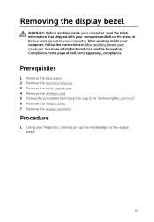
...computer, read the safety information that shipped with your computer and follow the instructions in "Removing the palm rest". 6 Remove the hinge covers. 7 Remove the display assembly. Prerequisites 1 Remove the base panel. 2 Remove the memory modules. 3 Remove the solid-state drives. 4 Remove the wireless card. 5 Follow the procedure... follow the steps in Before working inside your computer. For more safety best practices, see the Regulatory Compliance home page at dell.com/regulatory_compliance. After working inside edges of the display bezel. 83 Procedure 1 Using your computer.
...computer, read the safety information that shipped with your computer and follow the instructions in "Removing the palm rest". 6 Remove the hinge covers. 7 Remove the display assembly. Prerequisites 1 Remove the base panel. 2 Remove the memory modules. 3 Remove the solid-state drives. 4 Remove the wireless card. 5 Follow the procedure... follow the steps in Before working inside your computer. For more safety best practices, see the Regulatory Compliance home page at dell.com/regulatory_compliance. After working inside edges of the display bezel. 83 Procedure 1 Using your computer.

Service Manual
Page 84
2 Carefully lift the display bezel and turn it over. 1 display bezel 3 Lift the latches and disconnect the display-board cables from the logo board. 84
2 Carefully lift the display bezel and turn it over. 1 display bezel 3 Lift the latches and disconnect the display-board cables from the logo board. 84

Service Manual
Page 85
4 Peel off the adhesive tape and disconnect the logo-board cable from the logo board. 1 logo board 3 adhesive tape 2 display-board cables (3) 4 logo-board cable 85
4 Peel off the adhesive tape and disconnect the logo-board cable from the logo board. 1 logo board 3 adhesive tape 2 display-board cables (3) 4 logo-board cable 85


