
Alienware Graphics Amplifier Users Guide
Page 5
... cards, handle them by their electrical outlets. 2 Disconnect all cables such as telephone cables, network cables and so on, from your device. 3 Disconnect all attached peripherals, such as keyboard, mouse, monitor, and so on the configuration you finish working inside the device, replace all power sources before connecting to protect your device from potential damage and ensure your personal safety. WARNING: Disconnect all covers, panels, and screws before opening...
... cards, handle them by their electrical outlets. 2 Disconnect all cables such as telephone cables, network cables and so on, from your device. 3 Disconnect all attached peripherals, such as keyboard, mouse, monitor, and so on the configuration you finish working inside the device, replace all power sources before connecting to protect your device from potential damage and ensure your personal safety. WARNING: Disconnect all covers, panels, and screws before opening...

Alienware Graphics Amplifier Users Guide
Page 7
After Working Inside Your Alienware Graphics Amplifier CAUTION: Leaving stray or loose screws inside your device may severely damage your device. 1 Replace all screws and make sure that no stray screws remain inside your device. 2 Connect any external devices, peripherals, and cables you removed before working on your device. 3 Replace any media cards, discs, and any other part(s) that you removed before working on your device. 4 Connect your device and all attached devices to their electrical outlets. 5 Turn on your device. 7
After Working Inside Your Alienware Graphics Amplifier CAUTION: Leaving stray or loose screws inside your device may severely damage your device. 1 Replace all screws and make sure that no stray screws remain inside your device. 2 Connect any external devices, peripherals, and cables you removed before working on your device. 3 Replace any media cards, discs, and any other part(s) that you removed before working on your device. 4 Connect your device and all attached devices to their electrical outlets. 5 Turn on your device. 7

Alienware Graphics Amplifier Users Guide
Page 36
... Start → Help and Support. NOTE: Availability varies by -step see Alienware.com. Open the Search charm, type Help and Support in your computer Alienwareservices Contacting Alienware To contact Alienware for help on your purchase invoice, packing slip, bill, or Dell product catalog. Windows 7 - and services Troubleshooting information, user manuals, setup instructions, product specifications, technical help resources: Self-Help Information Self-Help Options Accessing Windows Help Windows 8.1 - Information about Alienware products See alienware...
... Start → Help and Support. NOTE: Availability varies by -step see Alienware.com. Open the Search charm, type Help and Support in your computer Alienwareservices Contacting Alienware To contact Alienware for help on your purchase invoice, packing slip, bill, or Dell product catalog. Windows 7 - and services Troubleshooting information, user manuals, setup instructions, product specifications, technical help resources: Self-Help Information Self-Help Options Accessing Windows Help Windows 8.1 - Information about Alienware products See alienware...

Service Manual
Page 3
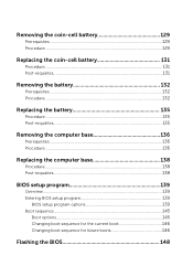
Contents Before working inside your computer 12 Before you begin 12 Safety instructions 12 Recommended tools 13 After working inside your computer 15 Removing the base panel 16 Procedure...16 Replacing the base panel 19 Procedure...19 Removing the memory modules 20 Prerequisites...20 Procedure...20 Replacing the memory modules 22 Procedure...22 Post-requisites 23 Removing the solid-state drives 24 Prerequisites...24 Procedure...24 Replacing the solid-state drives 26 Procedure...26 Post-requisites 26
Contents Before working inside your computer 12 Before you begin 12 Safety instructions 12 Recommended tools 13 After working inside your computer 15 Removing the base panel 16 Procedure...16 Replacing the base panel 19 Procedure...19 Removing the memory modules 20 Prerequisites...20 Procedure...20 Replacing the memory modules 22 Procedure...22 Post-requisites 23 Removing the solid-state drives 24 Prerequisites...24 Procedure...24 Replacing the solid-state drives 26 Procedure...26 Post-requisites 26
Service Manual
Page 10
... Removing the battery 132 Prerequisites 132 Procedure...132 Replacing the battery 135 Procedure...135 Post-requisites 135 Removing the computer base 136 Prerequisites 136 Procedure...136 Replacing the computer base 138 Procedure...138 Post-requisites 138 BIOS setup program 139 Overview...139 Entering BIOS setup program 139 BIOS setup program options 139 Boot sequence 145 Boot options 145 Changing boot sequence for the current boot 146 Changing boot sequence for future boots 146 Flashing...
... Removing the battery 132 Prerequisites 132 Procedure...132 Replacing the battery 135 Procedure...135 Post-requisites 135 Removing the computer base 136 Prerequisites 136 Procedure...136 Replacing the computer base 138 Procedure...138 Post-requisites 138 BIOS setup program 139 Overview...139 Entering BIOS setup program 139 BIOS setup program options 139 Boot sequence 145 Boot options 145 Changing boot sequence for the current boot 146 Changing boot sequence for future boots 146 Flashing...
Service Manual
Page 13
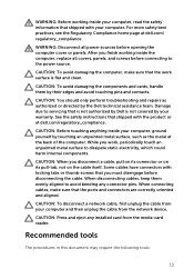
..., replace all power sources before opening the computer cover or panels. Recommended tools The procedures in this document may require the following tools: 13 After you must disengage before connecting to dissipate static electricity, which could harm internal components. Damage due to servicing that the work , periodically touch an unpainted metal surface to the power source. When disconnecting cables, keep them by Dell...
..., replace all power sources before opening the computer cover or panels. Recommended tools The procedures in this document may require the following tools: 13 After you must disengage before connecting to dissipate static electricity, which could harm internal components. Damage due to servicing that the work , periodically touch an unpainted metal surface to the power source. When disconnecting cables, keep them by Dell...
Service Manual
Page 15
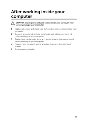
After working inside your computer CAUTION: Leaving stray or loose screws inside your computer may severely damage your computer. 1 Replace all screws and make sure that no stray screws remain inside your computer. 2 Connect any external devices, peripherals, and cables you removed before working on your computer. 3 Replace any media cards, discs, and any other parts that you removed before working on your computer. 4 Connect your computer and all attached devices to their electrical outlets. 5 Turn on your computer. 15
After working inside your computer CAUTION: Leaving stray or loose screws inside your computer may severely damage your computer. 1 Replace all screws and make sure that no stray screws remain inside your computer. 2 Connect any external devices, peripherals, and cables you removed before working on your computer. 3 Replace any media cards, discs, and any other parts that you removed before working on your computer. 4 Connect your computer and all attached devices to their electrical outlets. 5 Turn on your computer. 15
Service Manual
Page 20
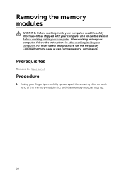
... panel. After working inside your computer, follow the steps in After working inside your computer. Procedure 1 Using your fingertips, carefully spread apart the securing clips on each end of the memory-module slot until the memory module pops up. 20 Removing the memory modules WARNING: Before working inside your computer, read the safety information that shipped with your computer and follow the instructions in Before working...
... panel. After working inside your computer, follow the steps in After working inside your computer. Procedure 1 Using your fingertips, carefully spread apart the securing clips on each end of the memory-module slot until the memory module pops up. 20 Removing the memory modules WARNING: Before working inside your computer, read the safety information that shipped with your computer and follow the instructions in Before working...

Service Manual
Page 36
... steps in After working inside your computer. Prerequisites 1 Remove the base panel. 2 Remove the memory modules. 3 Remove the solid-state drives. Procedure 1 Remove the keyboard cable, keyboard-backlight cable, and macro-keys cable from the routing guides on the computer base. 36 Removing the palm rest WARNING: Before working inside your computer, read the safety information that shipped with your computer and follow the instructions in Before working inside your...
... steps in After working inside your computer. Prerequisites 1 Remove the base panel. 2 Remove the memory modules. 3 Remove the solid-state drives. Procedure 1 Remove the keyboard cable, keyboard-backlight cable, and macro-keys cable from the routing guides on the computer base. 36 Removing the palm rest WARNING: Before working inside your computer, read the safety information that shipped with your computer and follow the instructions in Before working inside your...
Service Manual
Page 49
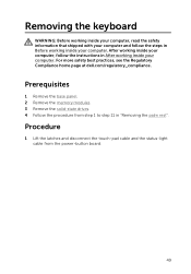
... at dell.com/regulatory_compliance. Removing the keyboard WARNING: Before working inside your computer, read the safety information that shipped with your computer and follow the instructions in After working inside your computer. After working inside your computer, follow the steps in Before working inside your computer. Prerequisites 1 Remove the base panel. 2 Remove the memory modules. 3 Remove the solid-state drives. 4 Follow the procedure from the power-button board...
... at dell.com/regulatory_compliance. Removing the keyboard WARNING: Before working inside your computer, read the safety information that shipped with your computer and follow the instructions in After working inside your computer. After working inside your computer, follow the steps in Before working inside your computer. Prerequisites 1 Remove the base panel. 2 Remove the memory modules. 3 Remove the solid-state drives. 4 Follow the procedure from the power-button board...
Service Manual
Page 56
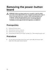
... at dell.com/regulatory_compliance. Prerequisites 1 Remove the base panel. 2 Remove the memory modules. 3 Remove the solid-state drives. 4 Follow the procedure from the power-button board. 56 Procedure 1 Lift the latches and disconnect the touch-pad cable and status-light cable from step 1 to step 12 in "Removing the palm rest". After working inside your computer, follow the steps in Before working inside your computer. Removing the power-button board WARNING: Before working inside...
... at dell.com/regulatory_compliance. Prerequisites 1 Remove the base panel. 2 Remove the memory modules. 3 Remove the solid-state drives. 4 Follow the procedure from the power-button board. 56 Procedure 1 Lift the latches and disconnect the touch-pad cable and status-light cable from step 1 to step 12 in "Removing the palm rest". After working inside your computer, follow the steps in Before working inside your computer. Removing the power-button board WARNING: Before working inside...
Service Manual
Page 83
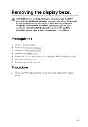
... with your computer and follow the instructions in After working inside your fingertips, carefully pry up the inside your computer. After working inside your computer, follow the steps in "Removing the palm rest". 6 Remove the hinge covers. 7 Remove the display assembly. Procedure 1 Using your computer. Prerequisites 1 Remove the base panel. 2 Remove the memory modules. 3 Remove the solid-state drives. 4 Remove the wireless card. 5 Follow the procedure from step 1 to...
... with your computer and follow the instructions in After working inside your fingertips, carefully pry up the inside your computer. After working inside your computer, follow the steps in "Removing the palm rest". 6 Remove the hinge covers. 7 Remove the display assembly. Procedure 1 Using your computer. Prerequisites 1 Remove the base panel. 2 Remove the memory modules. 3 Remove the solid-state drives. 4 Remove the wireless card. 5 Follow the procedure from step 1 to...

Service Manual
Page 114
... board. Prerequisites 1 Remove the base panel. 2 Remove the memory modules. 3 Remove the solid-state drives. 4 Remove the wireless card. 5 Follow the procedure from step 1 to the BIOS using the BIOS setup program. You must enter the Service Tag in the BIOS setup program after you replace the system board. NOTE: Replacing the system board removes any changes you have made to step 11 in the system board. NOTE: Before disconnecting the cables from the system board. 114 After working...
... board. Prerequisites 1 Remove the base panel. 2 Remove the memory modules. 3 Remove the solid-state drives. 4 Remove the wireless card. 5 Follow the procedure from step 1 to the BIOS using the BIOS setup program. You must enter the Service Tag in the BIOS setup program after you replace the system board. NOTE: Replacing the system board removes any changes you have made to step 11 in the system board. NOTE: Before disconnecting the cables from the system board. 114 After working...
Service Manual
Page 129
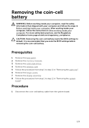
... follow the instructions in "Removing the system board". Procedure 1 Disconnect the coin-cell battery cable from step 1 to step 11 in After working inside your computer. For more safety best practices, see the Regulatory Compliance home page at dell.com/regulatory_compliance. Prerequisites 1 Remove the base panel. 2 Remove the memory modules. 3 Remove the solid-state drives. 4 Remove the wireless card. 5 Follow the procedure from step 1 to default. After working inside...
... follow the instructions in "Removing the system board". Procedure 1 Disconnect the coin-cell battery cable from step 1 to step 11 in After working inside your computer. For more safety best practices, see the Regulatory Compliance home page at dell.com/regulatory_compliance. Prerequisites 1 Remove the base panel. 2 Remove the memory modules. 3 Remove the solid-state drives. 4 Remove the wireless card. 5 Follow the procedure from step 1 to default. After working inside...
Service Manual
Page 138
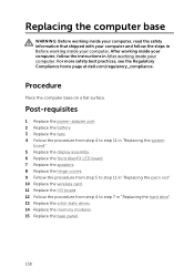
... Compliance home page at dell.com/regulatory_compliance. Post-requisites 1 Replace the power-adapter port. 2 Replace the battery. 3 Replace the fans. 4 Follow the procedure from step 4 to step 11 in "Replacing the system board". 5 Replace the display assembly. 6 Replace the front AlienFX LED board. 7 Replace the speakers. 8 Replace the hinge covers. 9 Follow the procedure from step 5 to step 11 in "Replacing the palm rest". 10 Replace the wireless card. 11 Replace the I/O board. 12 Follow the...
... Compliance home page at dell.com/regulatory_compliance. Post-requisites 1 Replace the power-adapter port. 2 Replace the battery. 3 Replace the fans. 4 Follow the procedure from step 4 to step 11 in "Replacing the system board". 5 Replace the display assembly. 6 Replace the front AlienFX LED board. 7 Replace the speakers. 8 Replace the hinge covers. 9 Follow the procedure from step 5 to step 11 in "Replacing the palm rest". 10 Replace the wireless card. 11 Replace the I/O board. 12 Follow the...
Service Manual
Page 141
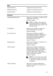
... Machine Monitor (VMM) to disable or enable the Intel Virtualization technology. Default: Enabled Allows you to use the additional hardware capabilities provided by Intel(R) Virtualization Technology for Direct I /O. Default: Enabled Allows you to enable or disable the USB emulation feature. This feature defines how the BIOS, in the absence of USB device (floppy, hard drive, or memory key) when this option is turned off or in standby mode. 141 Allows you to charge USB devices...
... Machine Monitor (VMM) to disable or enable the Intel Virtualization technology. Default: Enabled Allows you to use the additional hardware capabilities provided by Intel(R) Virtualization Technology for Direct I /O. Default: Enabled Allows you to enable or disable the USB emulation feature. This feature defines how the BIOS, in the absence of USB device (floppy, hard drive, or memory key) when this option is turned off or in standby mode. 141 Allows you to charge USB devices...
Service Manual
Page 142
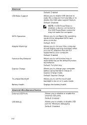
... should display warning messages when you to charge your computer. Default: Enabled Allows you to enable USB devices to wake the computer from standby or to disable the USB wake support feature. Advanced USB Wake Support SATA Operation Adapter Warnings Function Key Behavior Express Charge Touchpad Backlight Battery Health Default: Enabled Allows you to enable or disable USB port for Windows debugging. Default: Enabled Allows you to configure the operating mode of the integrated SATA harddrive controller. Allows you to set the touch pad backlight...
... should display warning messages when you to charge your computer. Default: Enabled Allows you to enable USB devices to wake the computer from standby or to disable the USB wake support feature. Advanced USB Wake Support SATA Operation Adapter Warnings Function Key Behavior Express Charge Touchpad Backlight Battery Health Default: Enabled Allows you to enable or disable USB port for Windows debugging. Default: Enabled Allows you to configure the operating mode of the integrated SATA harddrive controller. Allows you to set the touch pad backlight...
Service Manual
Page 145
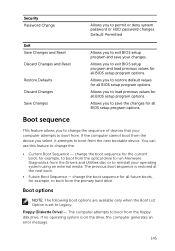
... error message. 145 Boot options NOTE: The following boot options are available only when the Boot List Option is set to boot from the floppy disk drive. The computer attempts to Legacy. If the computer cannot boot from the device you select, it attempts to exit BIOS setup program and save the changes for example, to permit or deny system password or HDD password changes. Default: Permitted Exit Save Changes and Reset Discard Changes and Reset Restore Defaults...
... error message. 145 Boot options NOTE: The following boot options are available only when the Boot List Option is set to boot from the floppy disk drive. The computer attempts to Legacy. If the computer cannot boot from the device you select, it attempts to exit BIOS setup program and save the changes for example, to permit or deny system password or HDD password changes. Default: Permitted Exit Save Changes and Reset Discard Changes and Reset Restore Defaults...
Service Manual
Page 146
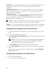
... error message. Insert the memory device into a USB connector and restart the computer. Changing boot sequence for future boots 1 Enter BIOS setup program. The Boot Options appears, listing all available boot devices. 4 On the Boot Options, select the device you want to a USB device, the device must be bootable. CD/DVD/CD-RW Drive - NOTE: To boot to boot from the network. The computer attempts to a USB hard drive, highlight USB Hard Disk and press Enter. Network - For example, if you see the Microsoft Windows...
... error message. Insert the memory device into a USB connector and restart the computer. Changing boot sequence for future boots 1 Enter BIOS setup program. The Boot Options appears, listing all available boot devices. 4 On the Boot Options, select the device you want to a USB device, the device must be bootable. CD/DVD/CD-RW Drive - NOTE: To boot to boot from the network. The computer attempts to a USB hard drive, highlight USB Hard Disk and press Enter. Network - For example, if you see the Microsoft Windows...

Service Manual
Page 147
NOTE: Note your current boot sequence in case you want to restore it. 3 Navigate to Set Boot Priority to configure the boot priority. 4 Use the arrow keys to highlight the boot priority and press Enter to display the different devices. 5 Select the device and press Enter to access the menu. 2 Use the arrow keys to highlight the Boot menu option and press Enter to set the boot priority. 147
NOTE: Note your current boot sequence in case you want to restore it. 3 Navigate to Set Boot Priority to configure the boot priority. 4 Use the arrow keys to highlight the boot priority and press Enter to display the different devices. 5 Select the device and press Enter to access the menu. 2 Use the arrow keys to highlight the Boot menu option and press Enter to set the boot priority. 147


