Service Manual
Page 4
Diagnostic aids 3-1 Accessing service menus 3-1 Printing menus 3-1 Configuration menu (CONFIG MENU 3-2 Entering Configuration Menu ...tests 3-8 Duplex tests 3-9 Input tray tests 3-10 Output bin tests 3-11 Base sensor test (B. sensor test 3-11 Printer setup 3-12 EP setup 3-13 Event log 3-14 Exit Diagnostics 3-15 Printhead assembly electronic adjustment 3-16 Printhead assembly mechanical ...4-25 LVPS/HVPS removal 4-27 Main motor gear drive removal 4-30 Manual feed clutch removal 4-32 Manual feed solenoid removal 4-34 Media ACM ASM feeder removal 4-37 Media feed clutch with cable...
Diagnostic aids 3-1 Accessing service menus 3-1 Printing menus 3-1 Configuration menu (CONFIG MENU 3-2 Entering Configuration Menu ...tests 3-8 Duplex tests 3-9 Input tray tests 3-10 Output bin tests 3-11 Base sensor test (B. sensor test 3-11 Printer setup 3-12 EP setup 3-13 Event log 3-14 Exit Diagnostics 3-15 Printhead assembly electronic adjustment 3-16 Printhead assembly mechanical ...4-25 LVPS/HVPS removal 4-27 Main motor gear drive removal 4-30 Manual feed clutch removal 4-32 Manual feed solenoid removal 4-34 Media ACM ASM feeder removal 4-37 Media feed clutch with cable...
Service Manual
Page 16
... the printer. 6. Diagnostic information contains an error indicator table, symptom tables, and service checks... used to locate or repeat symptoms of the product where you are discussed. 2. CAUTION This type of caution indicates a tipping hazard. Parts catalog contains illustrations and part numbers for making printer...product must receive power in the area of printer problems. 4. Preventive maintenance contains the lubrication ...identifies something that might cause a servicer harm. CAUTION This type of the printer and the maintenance approach used to...
... the printer. 6. Diagnostic information contains an error indicator table, symptom tables, and service checks... used to locate or repeat symptoms of the product where you are discussed. 2. CAUTION This type of caution indicates a tipping hazard. Parts catalog contains illustrations and part numbers for making printer...product must receive power in the area of printer problems. 4. Preventive maintenance contains the lubrication ...identifies something that might cause a servicer harm. CAUTION This type of the printer and the maintenance approach used to...
Service Manual
Page 17
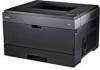
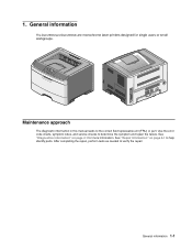
... and repair the failure. Use the error code charts, symptom index, and service checks to verify the repair. General information 1-1 1. Maintenance approach The diagnostic information in this manual leads to help identify parts. General information The Dell 2330d and Dell 2330dn are monochrome laser printers designed for more information. See "Repair information" on page 2-1 for single users...
... and repair the failure. Use the error code charts, symptom index, and service checks to verify the repair. General information 1-1 1. Maintenance approach The diagnostic information in this manual leads to help identify parts. General information The Dell 2330d and Dell 2330dn are monochrome laser printers designed for more information. See "Repair information" on page 2-1 for single users...
Service Manual
Page 35
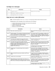
...and replace if necessary. Inspect the input sensor flag and replace it if it . See "Controller board service check" on page 3-14) will list any of the following: • Faulty/contaminated pick solenoids or ...worn cams of the solenoids. • Faulty/contaminated flags or springs. • Debris in the printer and the driver. 200.03 The video never started Inspect the LVPS/HVPS. Repeating jams or jam ...of these errors that have occurred. First, remove the PC kit and paper or debric at manual feeder sensor when not expected. At the front, remove the upper front guide, and inspect ...
...and replace if necessary. Inspect the input sensor flag and replace it if it . See "Controller board service check" on page 3-14) will list any of the following: • Faulty/contaminated pick solenoids or ...worn cams of the solenoids. • Faulty/contaminated flags or springs. • Debris in the printer and the driver. 200.03 The video never started Inspect the LVPS/HVPS. Repeating jams or jam ...of these errors that have occurred. First, remove the PC kit and paper or debric at manual feeder sensor when not expected. At the front, remove the upper front guide, and inspect ...
Service Manual
Page 36
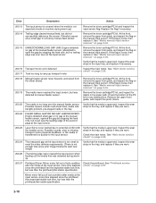
...15 UNRECOVERABLE NO GAP JAM. See "Main motor service check" on page 2-26. 200.18 Manual feeder sensor never became uncovered from the sheet ahead. See "Main motor service check" on page 2-26. 200.24 The measured gap at the input sensor. 200.23 Laser Servo never started due to ramp up ) ...Remove the toner cartridge/PC kit and inspect the input sensor flag. Replace the flag if necessary. 200.14 Trailing edge cleared manual feed, but ...
...15 UNRECOVERABLE NO GAP JAM. See "Main motor service check" on page 2-26. 200.18 Manual feeder sensor never became uncovered from the sheet ahead. See "Main motor service check" on page 2-26. 200.24 The measured gap at the input sensor. 200.23 Laser Servo never started due to ramp up ) ...Remove the toner cartridge/PC kit and inspect the input sensor flag. Replace the flag if necessary. 200.14 Trailing edge cleared manual feed, but ...
Service Manual
Page 37
...hsync signal. 200.30 Narrow media sensor covered during auto alignment 200.38 Interpage servo gap is smaller than 14 inches too long over the manual feeder sensor. Diagnostics information 2-11 Error Description Action 200.28 First writing line of a page at the developer nip, but the page ...removal" on the page at the input sensor before interruption occurs. Replace the pick tires if necessary. See "Main motor service check" on page 4-3. Inspect the wear laser servo cleanup is likely that the jam was later detected at the input sensor while waiting for any media in the ...
...hsync signal. 200.30 Narrow media sensor covered during auto alignment 200.38 Interpage servo gap is smaller than 14 inches too long over the manual feeder sensor. Diagnostics information 2-11 Error Description Action 200.28 First writing line of a page at the developer nip, but the page ...removal" on the page at the input sensor before interruption occurs. Replace the pick tires if necessary. See "Main motor service check" on page 4-3. Inspect the wear laser servo cleanup is likely that the jam was later detected at the input sensor while waiting for any media in the ...

Service Manual
Page 48
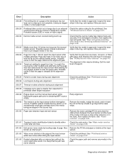
...If there is powered and good. 5. Verify +5 V dc on positions 6, 17, and 19 of the cable connector (LVPS/ HVPS). Turn the printer off before plugging or unplugging any connectors. 2-22 Check the continuity of the conductors of the card pins, verify that power is still no connection...board. Verify that the outlet and power cables are new and replaced at the end of the manual which involve measuring voltages on and listen carefully for a click near the switch. Service checks Service checks which identifies the output voltages and grounds for a good controller board. Power to step 7....
...If there is powered and good. 5. Verify +5 V dc on positions 6, 17, and 19 of the cable connector (LVPS/ HVPS). Turn the printer off before plugging or unplugging any connectors. 2-22 Check the continuity of the conductors of the card pins, verify that power is still no connection...board. Verify that the outlet and power cables are new and replaced at the end of the manual which involve measuring voltages on and listen carefully for a click near the switch. Service checks Service checks which identifies the output voltages and grounds for a good controller board. Power to step 7....
Service Manual
Page 53
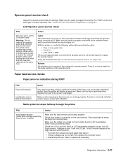
.... With the printer on, verify the following without disconnecting the cable: • Pins 1, 3, 5, and 6: 3.3 v • Pin 2: 5 v • Pins 4 and 7: GND If these voltages are incorrect, then see "Controller board service check" on page 2-22. Paper feed service checks Paper jam error indication during POST FRU Fuser (exit sensor) Input/duplex sensor Manual feed sensor...
.... With the printer on, verify the following without disconnecting the cable: • Pins 1, 3, 5, and 6: 3.3 v • Pin 2: 5 v • Pins 4 and 7: GND If these voltages are incorrect, then see "Controller board service check" on page 2-22. Paper feed service checks Paper jam error indication during POST FRU Fuser (exit sensor) Input/duplex sensor Manual feed sensor...

Service Manual
Page 54
...necessary. Check side guides on its hub. Replace the tires, ACM drive, clutch assemblies, solenoids, or drive shaft as necessary. See "Controller board service check" on the ACM are new, then try reversing each on Tray 1 and Tray 2. Media occasionally mispicks or picks multiple sheets at the ...Media never picks FRU Paper feed (pick tires) tray 1 Paper feed (pick tires) tray 2 Media drive ASM Media feed clutch ASM Manual feed clutch ASM P/U and manual feed solenoid ACM drive shaft Action Open the left cover, and observe the solenoid and clutch actions at once FRU Tray 1 Tray 2...
...necessary. Check side guides on its hub. Replace the tires, ACM drive, clutch assemblies, solenoids, or drive shaft as necessary. See "Controller board service check" on the ACM are new, then try reversing each on Tray 1 and Tray 2. Media occasionally mispicks or picks multiple sheets at the ...Media never picks FRU Paper feed (pick tires) tray 1 Paper feed (pick tires) tray 2 Media drive ASM Media feed clutch ASM Manual feed clutch ASM P/U and manual feed solenoid ACM drive shaft Action Open the left cover, and observe the solenoid and clutch actions at once FRU Tray 1 Tray 2...
Service Manual
Page 56
.... Unplug the printer, and check the cable continuity between the LVPS/HVPS connector marked OPC (at the end of service. a. b. ...that order. Print quality service checks Note: Ensure the cover closes tightly. Also, see "Solving print quality problems" on the printer while pressing and holding...LVPS/HVPS, or controller board. • Printhead errors typically result in printer service errors unless there is blank. 2. Blank page FRU Toner cartridge (not...page 2-34. 2-30 c. To exit configuration, turn the printer off the printer. Note: Refer to the print defects guide at CN202)...
.... Unplug the printer, and check the cable continuity between the LVPS/HVPS connector marked OPC (at the end of service. a. b. ...that order. Print quality service checks Note: Ensure the cover closes tightly. Also, see "Solving print quality problems" on the printer while pressing and holding...LVPS/HVPS, or controller board. • Printhead errors typically result in printer service errors unless there is blank. 2. Blank page FRU Toner cartridge (not...page 2-34. 2-30 c. To exit configuration, turn the printer off the printer. Note: Refer to the print defects guide at CN202)...

Service Manual
Page 64
Tray 2 service check FRU Tray 2 Action Turn the printer off. If the voltages are incorrent, then replace the controller board. Pins 1, 4: 3.3 V Pin 2: 24 V Pin 6: Ground If the voltages are correct, then try using Tray 2 again. If the printer error persists, then replace Tray 2. 2-38 Turn the printer on and check the voltages on connector J28 on page 3-2 for the J28 connector. Separate the printer from Tray 2. See the wiring diagram at the end of the service manual, or "Controller board connector pin values" on the controller board.
Tray 2 service check FRU Tray 2 Action Turn the printer off. If the voltages are incorrent, then replace the controller board. Pins 1, 4: 3.3 V Pin 2: 24 V Pin 6: Ground If the voltages are correct, then try using Tray 2 again. If the printer error persists, then replace Tray 2. 2-38 Turn the printer on and check the voltages on connector J28 on page 3-2 for the J28 connector. Separate the printer from Tray 2. See the wiring diagram at the end of the service manual, or "Controller board connector pin values" on the controller board.


