Service Manual
Page 4
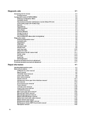
... ESD-sensitive parts 4-1 Removal procedures 4-2 ACM pick tire roller removal 4-3 Bezel removal 4-5 Controller board removal 4-6 Cover open sensor 4-8 Door mount removal 4-9 Duplex removal 4-11 Duplex/main motor gear drive interface removal 4-13 Fan removal 4-16 Front access door removal 4-17 Fuser removal 4-20 Left side cover removal 4-23 Lower front cover removal 4-25 LVPS/HVPS removal 4-27 Main motor gear drive removal 4-30 Manual feed...
... ESD-sensitive parts 4-1 Removal procedures 4-2 ACM pick tire roller removal 4-3 Bezel removal 4-5 Controller board removal 4-6 Cover open sensor 4-8 Door mount removal 4-9 Duplex removal 4-11 Duplex/main motor gear drive interface removal 4-13 Fan removal 4-16 Front access door removal 4-17 Fuser removal 4-20 Left side cover removal 4-23 Lower front cover removal 4-25 LVPS/HVPS removal 4-27 Main motor gear drive removal 4-30 Manual feed...
Service Manual
Page 34
...DO NOT POWER OFF Program Flash DO NOT POWER OFF Prog System Code DO NOT POWER OFF Ready Remove Paper Standard Bin Resetting Maint Cnt Valu Resetting PC Cnt Value Resetting the Printer Res Reduced Restoring Factory Defaults Std Bin Full Toner Low Tray Missing USM Waiting Action The... print. Warning: Do not turn the printer off while this message is displayed. The printer is reducing the resolution of the buffer. • Cancel the current job. 2-8 Res Reduced remains on the fuser. Note: When factory default settings are deleted. • All menu settings return to clear. Wait for...
...DO NOT POWER OFF Program Flash DO NOT POWER OFF Prog System Code DO NOT POWER OFF Ready Remove Paper Standard Bin Resetting Maint Cnt Valu Resetting PC Cnt Value Resetting the Printer Res Reduced Restoring Factory Defaults Std Bin Full Toner Low Tray Missing USM Waiting Action The... print. Warning: Do not turn the printer off while this message is displayed. The printer is reducing the resolution of the buffer. • Cancel the current job. 2-8 Res Reduced remains on the fuser. Note: When factory default settings are deleted. • All menu settings return to clear. Wait for...
Service Manual
Page 37
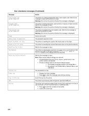
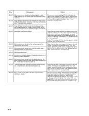
Inspect the wear laser servo cleanup is at the input sensor before interruption occurs. Retry alignment. 200... path. Timed out waiting for page from tray 1 did make it is approved. See "ACM pick tire roller removal" on page 2-37. 201.05 Restart attempted after hitting the input sensor Check the printhead. Call the next level...jam. Inspect the wear strips in the source tray. See "Fuser removal" on page 4-48. 200.32 Media more than expected for obstructions between input and exit sensor Remove the toner cartridge/PC kit and check for printhead offset target...
Inspect the wear laser servo cleanup is at the input sensor before interruption occurs. Retry alignment. 200... path. Timed out waiting for page from tray 1 did make it is approved. See "ACM pick tire roller removal" on page 2-37. 201.05 Restart attempted after hitting the input sensor Check the printhead. Call the next level...jam. Inspect the wear strips in the source tray. See "Fuser removal" on page 4-48. 200.32 Media more than expected for obstructions between input and exit sensor Remove the toner cartridge/PC kit and check for printhead offset target...
Service Manual
Page 38
... ) 202.25 Exit sensor never broke from sheet ahead of page heading toward the exit sensor. See "Fuser removal" on page 4-48. 2-12 If damage is located behind the fuser exit rollers, about mid printer. Open the rear door, and inspect the flag on the exit sensor. Note: Print a page with ...sensor and reversing solenoid removal" on page 4-20. 201.27 Page at fuser nip before sending to duplex. Often, the leading ...
... ) 202.25 Exit sensor never broke from sheet ahead of page heading toward the exit sensor. See "Fuser removal" on page 4-48. 2-12 If damage is located behind the fuser exit rollers, about mid printer. Open the rear door, and inspect the flag on the exit sensor. Note: Print a page with ...sensor and reversing solenoid removal" on page 4-20. 201.27 Page at fuser nip before sending to duplex. Often, the leading ...

Service Manual
Page 39
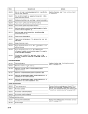
... tray and inspect the media path for obstructions between the rear cover ribs, the fuser exit rollers, and below. Replace it on page 4-3. See "ACM pick tire roller removal" on Tray 2.) If the error persists, then replace Tray 2. 242.10 Second pick attempt failed from Tray 1, no obstructions and the ... the antenna on a wireless unit), and inspect the flag of dc feed interrupts before losing them Check the connection with Tray 2. (Lift the printer and re-set it if necessary. 233.02 Feed error picking from the duplex. 233.03 Paper never reached the input sensor, but was detected...
... tray and inspect the media path for obstructions between the rear cover ribs, the fuser exit rollers, and below. Replace it on page 4-3. See "ACM pick tire roller removal" on Tray 2.) If the error persists, then replace Tray 2. 242.10 Second pick attempt failed from Tray 1, no obstructions and the ... the antenna on a wireless unit), and inspect the flag of dc feed interrupts before losing them Check the connection with Tray 2. (Lift the printer and re-set it if necessary. 233.02 Feed error picking from the duplex. 233.03 Paper never reached the input sensor, but was detected...
Service Manual
Page 42
... in the printer. This applies to converge. Toner service errors 929.00 929.01 929.02 Toner sensor error No home window No sensor transition (closed) Remove the toner cartridge, and shake it Try a different toner cartridge, if possible. Possible noisy thermistor signal. The ADC failed to the fuser and belt fusers. 924.00...
... in the printer. This applies to converge. Toner service errors 929.00 929.01 929.02 Toner sensor error No home window No sensor transition (closed) Remove the toner cartridge, and shake it Try a different toner cartridge, if possible. Possible noisy thermistor signal. The ADC failed to the fuser and belt fusers. 924.00...

Service Manual
Page 48
...3-6. 7. Disconnect the LVPS/HVPS cable from the other card. Verify that power is supplied to the controller board. See "Controller board removal" on page 2-27. Controller board service check Controller board service check FRU Action Controller board assembly Warning: Do not replace the operator...the settings from the controller board at J502. 3. Each card contains the printer settings. When either of these positions, turn the printer off and go to display lights or activate the drive motor, fuser, or fan, then check the following in each conductor of the controller...
...3-6. 7. Disconnect the LVPS/HVPS cable from the other card. Verify that power is supplied to the controller board. See "Controller board removal" on page 2-27. Controller board service check Controller board service check FRU Action Controller board assembly Warning: Do not replace the operator...the settings from the controller board at J502. 3. Each card contains the printer settings. When either of these positions, turn the printer off and go to display lights or activate the drive motor, fuser, or fan, then check the following in each conductor of the controller...
Service Manual
Page 58
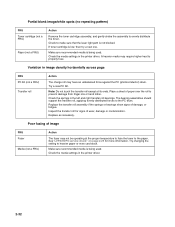
... (not a FRU) Action The fuser may require higher heat to heavier paper or even card stock. Inspect the transfer roll for more information. Try changing the setting to properly fuse. Check the media settings in the printer driver. See"LVPS/HVPS service check" on page 2-25 for signs ... fusing of damage, or fatigue. Partial blank image/white spots (no repeating pattern) FRU Toner cartridge (not a FRU) Paper (not a FRU) Action Remove the toner cartridge assembly, and gently shake the assembly to make sure that the laser light path is being used . Check the media settings in the...
... (not a FRU) Action The fuser may require higher heat to heavier paper or even card stock. Inspect the transfer roll for more information. Try changing the setting to properly fuse. Check the media settings in the printer driver. See"LVPS/HVPS service check" on page 2-25 for signs ... fusing of damage, or fatigue. Partial blank image/white spots (no repeating pattern) FRU Toner cartridge (not a FRU) Paper (not a FRU) Action Remove the toner cartridge assembly, and gently shake the assembly to make sure that the laser light path is being used . Check the media settings in the...
Service Manual
Page 60
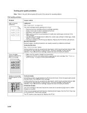
... the PC Kit, and recheck before replacing the toner cartridge. Try a different toner cartridge. Vertical or horizontal streaks appear on toner: • Remove the toner cartridge and print cartridge assembly. • Shake it from side to side to redistribute the toner. • Reinstall it, and recheck... be defective. If the lines are usually caused by the laser beam, which may be partially blocked. Toner smudges appear on page 2-33. The toner cartridge or fuser may be defective. Check those settings. With the printer off , clear the path or clean the lens. The ...
... the PC Kit, and recheck before replacing the toner cartridge. Try a different toner cartridge. Vertical or horizontal streaks appear on toner: • Remove the toner cartridge and print cartridge assembly. • Shake it from side to side to redistribute the toner. • Reinstall it, and recheck... be defective. If the lines are usually caused by the laser beam, which may be partially blocked. Toner smudges appear on page 2-33. The toner cartridge or fuser may be defective. Check those settings. With the printer off , clear the path or clean the lens. The ...

Service Manual
Page 61
...Replace the toner cartridge. • Select a different media type or form type setting from the printer driver. • Try a different type of paper. The print is getting light, but the printer has not indicated it from side to side to redistribute the toner. • Replace the toner..."Printhead service check" on page 2-37. • Also, see "Blank page" on the page. Replace the fuser. • Change the media texture setting in the software program. • Remove the toner cartridge, and gently shake it is expecting. • Choose a different fill pattern in the driver. ...
...Replace the toner cartridge. • Select a different media type or form type setting from the printer driver. • Try a different type of paper. The print is getting light, but the printer has not indicated it from side to side to redistribute the toner. • Replace the toner..."Printhead service check" on page 2-37. • Also, see "Blank page" on the page. Replace the fuser. • Change the media texture setting in the software program. • Remove the toner cartridge, and gently shake it is expecting. • Choose a different fill pattern in the driver. ...

Service Manual
Page 81
...to the location of the old printhead on the metal frame. Note: Skew is rotated relative to be correctly positioned after it has been removed. However, a mechanically misaligned printhead causes the horizontal lines to appear skewed while the vertical lines remain parallel to the vertical edges.There ...the pick roll (paper pick assembly) for wear, the paper path for obstructions, the fuser for proper setting, and the tray paper guides for skew. The entire image is caused by a sheet being fed through the printer while misaligned. Use a pencil to the media. See photo below. 6. Fold a ...
...to the location of the old printhead on the metal frame. Note: Skew is rotated relative to be correctly positioned after it has been removed. However, a mechanically misaligned printhead causes the horizontal lines to appear skewed while the vertical lines remain parallel to the vertical edges.There ...the pick roll (paper pick assembly) for wear, the paper path for obstructions, the fuser for proper setting, and the tray paper guides for skew. The entire image is caused by a sheet being fed through the printer while misaligned. Use a pencil to the media. See photo below. 6. Fold a ...

Service Manual
Page 92
Remove the three screws (D) from the left side of the printer. 10. 8. Disconnect the fuser link (C). C 9. Remove the door mounts. 4-10
Remove the three screws (D) from the left side of the printer. 10. 8. Disconnect the fuser link (C). C 9. Remove the door mounts. 4-10

Service Manual
Page 102
See "Rear exit guide assembly with sensor and reversing solenoid removal" on the cable connector cover (B), and remove. 4-20 Partially pull the fuser forward for better access. 4. Remove the two screws (A). 3. Push in on page 4-56. 2. Remove the rear exit guide. Fuser removal 1.
See "Rear exit guide assembly with sensor and reversing solenoid removal" on the cable connector cover (B), and remove. 4-20 Partially pull the fuser forward for better access. 4. Remove the two screws (A). 3. Push in on page 4-56. 2. Remove the rear exit guide. Fuser removal 1.

Service Manual
Page 104
E 8. Note: • Be careful to not damage the gears during the fuser installation. • Be sure to reinstall the AC cable during the fuser installation. 4-22 Disconnect the exit sensor cable (E) from the controller board. Remove the fuser. 7.
E 8. Note: • Be careful to not damage the gears during the fuser installation. • Be sure to reinstall the AC cable during the fuser installation. 4-22 Disconnect the exit sensor cable (E) from the controller board. Remove the fuser. 7.

Service Manual
Page 105
Remove the screw (B), and press the two latches (C) on the bottom of the left side cover. 1. Left side cover removal Note: • Leave the front door closed when removing the left side cover. • Make sure that the fuser cables are out of the way when removing the left side cover. A 3. B C Repair information 4-23 Remove the screw (A) from the rear left side of the printer. Remove the paper tray. 2.
Remove the screw (B), and press the two latches (C) on the bottom of the left side cover. 1. Left side cover removal Note: • Leave the front door closed when removing the left side cover. • Make sure that the fuser cables are out of the way when removing the left side cover. A 3. B C Repair information 4-23 Remove the screw (A) from the rear left side of the printer. Remove the paper tray. 2.

Service Manual
Page 109
B Repair information 4-27 LVPS/HVPS removal 1. See "Rear door and rear cover removal" on its top with the rear facing you. Remove the left side cover. A 5. Disconnect the fuser power cable (B). Remove the two screws (A) from the right rear foot assembly. Place the printer on page 4-54. 2. Note: Be careful to not mar the finish of the printer. 4. Remove the rear door cover. See "Left side cover removal" on page 4-23. 3.
B Repair information 4-27 LVPS/HVPS removal 1. See "Rear door and rear cover removal" on its top with the rear facing you. Remove the left side cover. A 5. Disconnect the fuser power cable (B). Remove the two screws (A) from the right rear foot assembly. Place the printer on page 4-54. 2. Note: Be careful to not mar the finish of the printer. 4. Remove the rear door cover. See "Left side cover removal" on page 4-23. 3.

Service Manual
Page 112
See "Left side cover removal" on its right side. Remove the four screws (B) from the front access door. Disconnect the fuser link (A) from the main motor gear drive. B 4-30 A 3. Place the printer on page 4-23. 2. Note: Be careful to not mar the finish of the printer. 4. Main motor gear drive removal 1. Remove the left side cover.
See "Left side cover removal" on its right side. Remove the four screws (B) from the front access door. Disconnect the fuser link (A) from the main motor gear drive. B 4-30 A 3. Place the printer on page 4-23. 2. Note: Be careful to not mar the finish of the printer. 4. Main motor gear drive removal 1. Remove the left side cover.

Service Manual
Page 114
Place the printer on page 4-23. 2. Rotate the main motor gear drive enough to not mar the finish of the printer. 4. Remove the left side cover. See "Left side cover removal" on its right side. Remove the four screws (B) from the main motor gear drive. B 5. A 3. Manual feed clutch removal 1. Open the front access door, and disconnect the fuser link (A). Note: Be careful to access the manual feed solenoid. 4-32
Place the printer on page 4-23. 2. Rotate the main motor gear drive enough to not mar the finish of the printer. 4. Remove the left side cover. See "Left side cover removal" on its right side. Remove the four screws (B) from the main motor gear drive. B 5. A 3. Manual feed clutch removal 1. Open the front access door, and disconnect the fuser link (A). Note: Be careful to access the manual feed solenoid. 4-32

Service Manual
Page 166
... 1-6 print quality pages using 2-30 print quality problems print media 1-7 service check 2-30 solving 2-34 printer symptom table 2-21 printhead service check 2-37 R registration 3-6 removals covers front access cover 4-6 procedures 4-2 S safety information xiii safety inspection guide 6-1 service checks 2-22 ...controller card 2-22 cooling fan 2-23 cover interlock switch 2-23 dead machine 2-24 fuser 2-25 LVPS/HVPS 2-25 main motor...
... 1-6 print quality pages using 2-30 print quality problems print media 1-7 service check 2-30 solving 2-34 printer symptom table 2-21 printhead service check 2-37 R registration 3-6 removals covers front access cover 4-6 procedures 4-2 S safety information xiii safety inspection guide 6-1 service checks 2-22 ...controller card 2-22 cooling fan 2-23 cover interlock switch 2-23 dead machine 2-24 fuser 2-25 LVPS/HVPS 2-25 main motor...


