Product Manual
Page 3
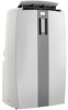
..., contact a qualified electrician. CAUTION: Do not leave this unit. PART IDENTIFICATION Air Outlet Signal Receptor Control Panel Air Intake (Evaporator) Air Intake Handle Air Outlet Hose Castor Water Outlet Drain Power Supply Cord IMPORTANT SAFETY INFORMATION READ ALL SAFETYEVFORMATIONBEFORE USING ELECTRICAL SPECIFICATIONS TABLE 1 Suggested Individual Branch Circuit 1) Check available power supply...
..., contact a qualified electrician. CAUTION: Do not leave this unit. PART IDENTIFICATION Air Outlet Signal Receptor Control Panel Air Intake (Evaporator) Air Intake Handle Air Outlet Hose Castor Water Outlet Drain Power Supply Cord IMPORTANT SAFETY INFORMATION READ ALL SAFETYEVFORMATIONBEFORE USING ELECTRICAL SPECIFICATIONS TABLE 1 Suggested Individual Branch Circuit 1) Check available power supply...
Product Manual
Page 5
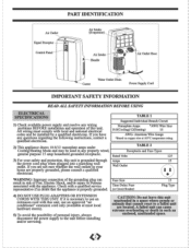
... "verticarrhorizontal" windows up to sect= each tube adapter with four screws through the back of the unit. INSTALLATION ACCESSORIES (FIG 1) Flexible Exhaust Hose (013cm) & Exhaust nozzle connector (2 pcs)... b) Secure each sliding section together. 1) Select a suitable location, making sure the window slider sections...Install the adjustable Window Slider Kit as required (see Fig. 3a & 3b). 4) Install the opposite end of the flexible exhaust hose into the window exhaust adapter. 5) Install the window exhaust adapter into the opening in the slider section, making sure you have ...
... "verticarrhorizontal" windows up to sect= each tube adapter with four screws through the back of the unit. INSTALLATION ACCESSORIES (FIG 1) Flexible Exhaust Hose (013cm) & Exhaust nozzle connector (2 pcs)... b) Secure each sliding section together. 1) Select a suitable location, making sure the window slider sections...Install the adjustable Window Slider Kit as required (see Fig. 3a & 3b). 4) Install the opposite end of the flexible exhaust hose into the window exhaust adapter. 5) Install the window exhaust adapter into the opening in the slider section, making sure you have ...
Product Manual
Page 7
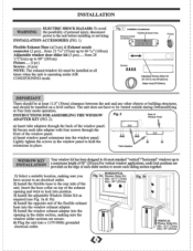
... MODE key will advance to select a suitable operating temperature setting. Fig. Fig. E) to a different mode setting (Cool- E Fig. OPERATION (cont'd) AIR CONDITIONING NOTE: The exhaust hose must be shown in Fan mode to 32°C (89°F). Each depression of water. 4) Operate the unit in the temperature display area of the...
... MODE key will advance to select a suitable operating temperature setting. Fig. Fig. E) to a different mode setting (Cool- E Fig. OPERATION (cont'd) AIR CONDITIONING NOTE: The exhaust hose must be shown in Fan mode to 32°C (89°F). Each depression of water. 4) Operate the unit in the temperature display area of the...
Product Manual
Page 8
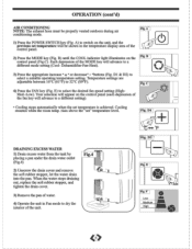
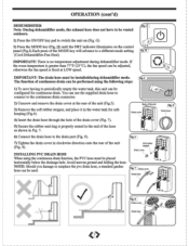
....I The function of the unit (Fig.5). G) 2) Press the MODE key (Fig. NOTE: Should you damage or misplace the pvc drain hose, a standard garden c hose can be placed horizontally below the drainage hole. H (Cool-Dehumidifier-Fan-Heat). IMPORTANT: There is fixed at the rear of continuous drain can... (Fig. 7). 5) Ensure the rubber seal ring is properly seated in the water tank for continuous drain. You can use the supplied drain hose to connect to a different mode setting . If the room temperature is greater than 77°F (25°C), the fan speed can be ...
....I The function of the unit (Fig.5). G) 2) Press the MODE key (Fig. NOTE: Should you damage or misplace the pvc drain hose, a standard garden c hose can be placed horizontally below the drainage hole. H (Cool-Dehumidifier-Fan-Heat). IMPORTANT: There is fixed at the rear of continuous drain can... (Fig. 7). 5) Ensure the rubber seal ring is properly seated in the water tank for continuous drain. You can use the supplied drain hose to connect to a different mode setting . If the room temperature is greater than 77°F (25°C), the fan speed can be ...
Product Manual
Page 9
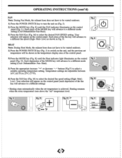
... (Fig. J) to switch on (Fig. Fig. Fig. J). 2) Press the MODE key (Fig. N. K HEAT Note: During Heat Mode, the exhaust hose does not have to be vented outdoors. 1) Press the POWER SWITCH key to turn the unit on the unit, and the previous set " temperature level.... Heat). 3) Press the appropriate increase " +" or decrease - OPERATING INSTRUCTIONS (cont'd) FAN Note: During Fan Mode, the exhaust hose does not have to be vented outdoors. 1) Press the POWER SWITCH key (Fig. Med- Fan- L c 4) Press the FAN key (Fig. K) until the ...
... (Fig. J) to switch on (Fig. Fig. Fig. J). 2) Press the MODE key (Fig. N. K HEAT Note: During Heat Mode, the exhaust hose does not have to be vented outdoors. 1) Press the POWER SWITCH key to turn the unit on the unit, and the previous set " temperature level.... Heat). 3) Press the appropriate increase " +" or decrease - OPERATING INSTRUCTIONS (cont'd) FAN Note: During Fan Mode, the exhaust hose does not have to be vented outdoors. 1) Press the POWER SWITCH key (Fig. Med- Fan- L c 4) Press the FAN key (Fig. K) until the ...
Product Manual
Page 12
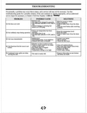
... test button on rear bottom and drain out water. 11 tank is minor, and a service call an authorized service depot for assistance, or Danby's Toll Free Number: 1-800-26- rature level. • Remove drain water from the drain tank 3) Unit runs intermittently 4) Unit functions ...filter. • Lower temp. setting. 5) Condensed water spills out when moving the unit. • The tank is normal. ,• Check the duct hose. • Close all windows/doors. • Move any heat sources from the drain tank • Press the reset button after resolving problem. • ...
... test button on rear bottom and drain out water. 11 tank is minor, and a service call an authorized service depot for assistance, or Danby's Toll Free Number: 1-800-26- rature level. • Remove drain water from the drain tank 3) Unit runs intermittently 4) Unit functions ...filter. • Lower temp. setting. 5) Condensed water spills out when moving the unit. • The tank is normal. ,• Check the duct hose. • Close all windows/doors. • Move any heat sources from the drain tank • Press the reset button after resolving problem. • ...


