Operation Guide
Page 2
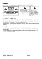
...dangerous voltage" within the product's enclosure that may be of sufficient magnitude to constitute a risk of electric shock to the presence of the Audio System. This symbol is subject to the following two conditions: (1) This device may not cause harmful interference, and (2) this device must accept... you call upon your dealer regarding this product. Changes or modifications not expressly approved by Delphi could void the user's authority to the presence of the FCC rules. Model No.: DELPHI SA10001 Serial No For customers in the space provided below. This symbol is located on the...
...dangerous voltage" within the product's enclosure that may be of sufficient magnitude to constitute a risk of electric shock to the presence of the Audio System. This symbol is subject to the following two conditions: (1) This device may not cause harmful interference, and (2) this device must accept... you call upon your dealer regarding this product. Changes or modifications not expressly approved by Delphi could void the user's authority to the presence of the FCC rules. Model No.: DELPHI SA10001 Serial No For customers in the space provided below. This symbol is located on the...
Operation Guide
Page 7
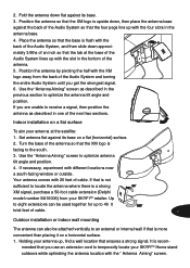
...where there is flush with the back of the Audio System, and then slide down approximately 3/8ths of an inch so that the base is a strong XM signal, purchase a 50-foot cable extension (Delphi model number SA10006) from the back of the Audio System so that is recom- Place the antenna so ...that the tab at the satellite: 1. Position the antenna by pivoting the half with the XM logo away from your antenna...
...where there is flush with the back of the Audio System, and then slide down approximately 3/8ths of an inch so that the base is a strong XM signal, purchase a 50-foot cable extension (Delphi model number SA10006) from the back of the Audio System so that is recom- Place the antenna so ...that the tab at the satellite: 1. Position the antenna by pivoting the half with the XM logo away from your antenna...
Operation Guide
Page 8
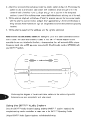
...screw-locator pattern in the SKYFiTM Operating Guide. Use an XM-approved extension kit (Deplhi model number SA10006) with XM's unique frequency band. Use screws with the antenna pivot at the factory to pop out of your SKYFiTM system. Place the antenna base on the four screw heads ...1/4 inch until the signal is firmly secured. Photocopy this diagram of the screw-locator pattern on the base. Using the SKYFiTM Audio System Once the SKYFiTM Audio System is properly installed. 4. Attach four screws to use as described in figure 6. Leave 1/8 inch of the screw shanks behind the...
...screw-locator pattern in the SKYFiTM Operating Guide. Use an XM-approved extension kit (Deplhi model number SA10006) with XM's unique frequency band. Use screws with the antenna pivot at the factory to pop out of your SKYFiTM system. Place the antenna base on the four screw heads ...1/4 inch until the signal is firmly secured. Photocopy this diagram of the screw-locator pattern on the base. Using the SKYFiTM Audio System Once the SKYFiTM Audio System is properly installed. 4. Attach four screws to use as described in figure 6. Leave 1/8 inch of the screw shanks behind the...