Product Manual
Page 33
...; VT100 terminal or PC with terminal-emulation software • Direct serial connection to the console port of -the-art wireless networking features. The D-Link Unified Access System enables wireless local area network (WLAN) deployment while providing state-of the D-Link Unified Switch • Remote system for management access with a Web browser, Telnet/SSH client, or SNMP...
...; VT100 terminal or PC with terminal-emulation software • Direct serial connection to the console port of -the-art wireless networking features. The D-Link Unified Access System enables wireless local area network (WLAN) deployment while providing state-of the D-Link Unified Switch • Remote system for management access with a Web browser, Telnet/SSH client, or SNMP...

Product Manual
Page 40
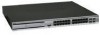
Front Panel View of the DWS-3026 as Shipped Figure 12. Front Panel View of the DWS-3024L as Shipped 40 © 2001- 2008 D-Link Corporation. Table 2 describes the LED indicators in more detail. Figure 11. D-Link Unified Access System User Manual Front Panel Components The front panel of the Switch consists of the DWS-3024 as Shipped Figure 13. Front Panel View of LED indicators for Power, Console, RPS, PoE, and Link/Act/Speed for each port on the Switch including 10GE Ports for optional modules and SFP port LEDs. All Rights Reserved.
Front Panel View of the DWS-3026 as Shipped Figure 12. Front Panel View of the DWS-3024L as Shipped 40 © 2001- 2008 D-Link Corporation. Table 2 describes the LED indicators in more detail. Figure 11. D-Link Unified Access System User Manual Front Panel Components The front panel of the Switch consists of the DWS-3024 as Shipped Figure 13. Front Panel View of LED indicators for Power, Console, RPS, PoE, and Link/Act/Speed for each port on the Switch including 10GE Ports for optional modules and SFP port LEDs. All Rights Reserved.
Product Manual
Page 41
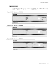
Figure 14. LED Indicators on DWS-3024L Figure 15. LED Indicators on DWS-3024 Figure 16. LED Indicators on the DWS-3026. 3 Installing the Hardware LED Indicators The Switch supports LED indicators for Power, Console, RPS, PoE, and Port LEDs including 10GE port LEDs for optional module inserts on DWS-3026 Hardware Overview 41
Figure 14. LED Indicators on DWS-3024L Figure 15. LED Indicators on DWS-3024 Figure 16. LED Indicators on the DWS-3026. 3 Installing the Hardware LED Indicators The Switch supports LED indicators for Power, Console, RPS, PoE, and Port LEDs including 10GE port LEDs for optional module inserts on DWS-3026 Hardware Overview 41

Product Manual
Page 42
... on the front panel of the device. The indicator is dark when the Switch is supporting devices attached to PoE and vice versa, press the LED Mode Select Button. LED Description LED Power Console RPS Link/Act/Speed and PoE Mode Port LEDs Description This LED lights green after powering... the Switch on the port (at the port, succession of a port corresponds to indicate the ready state ...
... on the front panel of the device. The indicator is dark when the Switch is supporting devices attached to PoE and vice versa, press the LED Mode Select Button. LED Description LED Power Console RPS Link/Act/Speed and PoE Mode Port LEDs Description This LED lights green after powering... the Switch on the port (at the port, succession of a port corresponds to indicate the ready state ...

Product Manual
Page 44
...it is missing or damaged, please contact your local D-Link Reseller for DWS-3000 Series Administrator's Guide and CLI Reference Guide 7. RS-232 console cable 6. One CD Kit for replacement. The rubber feet cushion the Switch, protect the casing from scratching other surfaces. 44 &#...169; 2001- 2008 D-Link Corporation. Mounting kit (two brackets and screws) 4....
...it is missing or damaged, please contact your local D-Link Reseller for DWS-3000 Series Administrator's Guide and CLI Reference Guide 7. RS-232 console cable 6. One CD Kit for replacement. The rubber feet cushion the Switch, protect the casing from scratching other surfaces. 44 &#...169; 2001- 2008 D-Link Corporation. Mounting kit (two brackets and screws) 4....

Product Manual
Page 55
... or enable the DHCP client. Configure the network information. - 4 Installing the D-Link Unified Access System Connecting the Switch to the Network After you perform the physical hardware installation, you can connect to the switch through Telnet or a Web browser from a host on the 10.0.0.0 network, enter... Baud rate: 115,000 bps - The default IP address of a Web browser or a Telnet client. You can connect to the switch through the console port (RS-232 DCE). To connect to execute the command. If you did not change the default settings. Press ENTER at the password...
... or enable the DHCP client. Configure the network information. - 4 Installing the D-Link Unified Access System Connecting the Switch to the Network After you perform the physical hardware installation, you can connect to the switch through Telnet or a Web browser from a host on the 10.0.0.0 network, enter... Baud rate: 115,000 bps - The default IP address of a Web browser or a Telnet client. You can connect to the switch through the console port (RS-232 DCE). To connect to execute the command. If you did not change the default settings. Press ENTER at the password...

