Product Manual
Page 9
... 11. Front Panel View of the DWS-3026 as Shipped 40 Figure 13. LED Indicators on DWS-3024 41 Figure 16. Rear panel view of DWS-3024/DWS-3024L 43 Figure 18. Inserting the Fiber-Optic Transceivers into the Switch (DWS-3026 48 Figure 26. Switch Connected to Switch 45 Figure 21. VAP Settings 93 ...DWS-3024L 41 Figure 15. Networks Available to the Wireless Client 98 Figure 43. LED Indicators on a Desktop or Shelf 45 Figure 20. Front Panel of the DEM-410CX 48 Figure 25. Front Panel of the DEM-410X 48 Figure 24. DWS-3026 with optional DEM-410X module installed 49 Figure 27. L2...
... 11. Front Panel View of the DWS-3026 as Shipped 40 Figure 13. LED Indicators on DWS-3024 41 Figure 16. Rear panel view of DWS-3024/DWS-3024L 43 Figure 18. Inserting the Fiber-Optic Transceivers into the Switch (DWS-3026 48 Figure 26. Switch Connected to Switch 45 Figure 21. VAP Settings 93 ...DWS-3024L 41 Figure 15. Networks Available to the Wireless Client 98 Figure 43. LED Indicators on a Desktop or Shelf 45 Figure 20. Front Panel of the DEM-410CX 48 Figure 25. Front Panel of the DEM-410X 48 Figure 24. DWS-3026 with optional DEM-410X module installed 49 Figure 27. L2...

Product Manual
Page 21
... not you have a peer group, the D-Link Unified Access System can manage up to 48 D-Link Access Points. The DWS-3024L Unified Switch can manage up to 24 D-Link Access Points, whereas the DWS-3024 and the DWS-3026 switches can support a total of 8000 wireless clients. You can handle up to 512 associated wireless clients (256 per radio). This chapter contains...
... not you have a peer group, the D-Link Unified Access System can manage up to 48 D-Link Access Points. The DWS-3024L Unified Switch can manage up to 24 D-Link Access Points, whereas the DWS-3024 and the DWS-3026 switches can support a total of 8000 wireless clients. You can handle up to 512 associated wireless clients (256 per radio). This chapter contains...

Product Manual
Page 22
...and clients. Access is useful for small networks with the following D-Link switches: • DWS-3024 (24 GE ports) • DWS-3024L (24 GE ports) • DWS-3026 (24 GE ports + 2 10G ports) D-Link Access Point The D-Link Access Point can centralize AP management and streamline the AP upgrade process...Administrator Web User Interface (UI) or command-line interface (CLI). The D-Link Unified Access System works with only a few APs. The second radio on the wired and wireless LAN. The Unified Switch user interface allows you to control the discovery, validation, authentication, and ...
...and clients. Access is useful for small networks with the following D-Link switches: • DWS-3024 (24 GE ports) • DWS-3024L (24 GE ports) • DWS-3026 (24 GE ports + 2 10G ports) D-Link Access Point The D-Link Access Point can centralize AP management and streamline the AP upgrade process...Administrator Web User Interface (UI) or command-line interface (CLI). The D-Link Unified Access System works with only a few APs. The second radio on the wired and wireless LAN. The Unified Switch user interface allows you to control the discovery, validation, authentication, and ...
Product Manual
Page 25
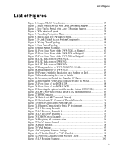
...-based management methods enables you use to 48 access points (DWS-3024 and DWS-3026) or 24 access points (DWS-3024L). Figure 3. Understanding the User Interfaces The D-Link Unified Access System enables centralized management of the D-Link Unified Access System up to configure and monitor the D-Link Unified Switch depends on your network size and requirements, and on the...
...-based management methods enables you use to 48 access points (DWS-3024 and DWS-3026) or 24 access points (DWS-3024L). Figure 3. Understanding the User Interfaces The D-Link Unified Access System enables centralized management of the D-Link Unified Access System up to configure and monitor the D-Link Unified Switch depends on your network size and requirements, and on the...

Product Manual
Page 31
...Wireless System Features and Standards Support 31 SYSLOG - IEEE 802.11h - IEEE 802.1X - 2001 Port Based Network Access Control - IEEE802.3af PoE Support • WLAN RF Features - Web Management (SSL support) - Tunneled and distributed forwarding - Peer-to 24 APs (DWS-3024L) or 48 APs (DWS-3024 and DWS-3026) per radio. Up to -peer WLAN switch...Management - The following list shows some of the D-Link Unified Access System - RF Scan - Dynamic Channel Assignment - Wireless Statistics - CLI - Station blacklisting - D-Link WLAN Private MIB • Simultaneous AP upgrade &#...
...Wireless System Features and Standards Support 31 SYSLOG - IEEE 802.11h - IEEE 802.1X - 2001 Port Based Network Access Control - IEEE802.3af PoE Support • WLAN RF Features - Web Management (SSL support) - Tunneled and distributed forwarding - Peer-to 24 APs (DWS-3024L) or 48 APs (DWS-3024 and DWS-3026) per radio. Up to -peer WLAN switch...Management - The following list shows some of the D-Link Unified Access System - RF Scan - Dynamic Channel Assignment - Wireless Statistics - CLI - Station blacklisting - D-Link WLAN Private MIB • Simultaneous AP upgrade &#...
Product Manual
Page 39
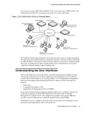
... • Installation - Package Contents - Installation Guidelines - Installing the SFP ports - Connecting the Switch and AP Directly - Hardware Overview 39 Connecting the Switch and AP through the L2/L3 Network - 3 Installing the Hardware This chapter provides instructions for installing the D-Link DWS-3024, DWS-3024L, and DWS-3026 switch hardware. Rear Panel Description - Connecting to the Network - Front Panel Components - Connecting...
... • Installation - Package Contents - Installation Guidelines - Installing the SFP ports - Connecting the Switch and AP Directly - Hardware Overview 39 Connecting the Switch and AP through the L2/L3 Network - 3 Installing the Hardware This chapter provides instructions for installing the D-Link DWS-3024, DWS-3024L, and DWS-3026 switch hardware. Rear Panel Description - Connecting to the Network - Front Panel Components - Connecting...

Product Manual
Page 40
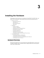
D-Link Unified Access System User Manual Front Panel Components The front panel of the Switch consists of the DWS-3026 as Shipped 40 © 2001- 2008 D-Link Corporation. Table 2 describes the LED indicators in more detail. Front Panel View of the DWS-3024L as Shipped Figure 13. Front Panel View of the DWS-3024 as Shipped Figure 12. Front Panel View of LED indicators for Power, Console, RPS, PoE, and Link/Act/Speed for each port on the Switch including 10GE Ports for optional modules and SFP port LEDs. All Rights Reserved. Figure 11.
D-Link Unified Access System User Manual Front Panel Components The front panel of the Switch consists of the DWS-3026 as Shipped 40 © 2001- 2008 D-Link Corporation. Table 2 describes the LED indicators in more detail. Front Panel View of the DWS-3024L as Shipped Figure 13. Front Panel View of the DWS-3024 as Shipped Figure 12. Front Panel View of LED indicators for Power, Console, RPS, PoE, and Link/Act/Speed for each port on the Switch including 10GE Ports for optional modules and SFP port LEDs. All Rights Reserved. Figure 11.
Product Manual
Page 41
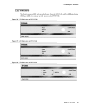
LED Indicators on DWS-3024 Figure 16. Figure 14. LED Indicators on DWS-3024L Figure 15. LED Indicators on the DWS-3026. 3 Installing the Hardware LED Indicators The Switch supports LED indicators for Power, Console, RPS, PoE, and Port LEDs including 10GE port LEDs for optional module inserts on DWS-3026 Hardware Overview 41
LED Indicators on DWS-3024 Figure 16. Figure 14. LED Indicators on DWS-3024L Figure 15. LED Indicators on the DWS-3026. 3 Installing the Hardware LED Indicators The Switch supports LED indicators for Power, Console, RPS, PoE, and Port LEDs including 10GE port LEDs for optional module inserts on DWS-3026 Hardware Overview 41

Product Manual
Page 43
... while a blinking green light indicates activity on each side of the Switch dissipate heat. These LEDs remain dark if there is no link/activity on the port. Rear Panel Description The AC power connector is no link/activity on the port. When a power failure occurs, the optional ..., and plug the male side of the DWS-3024/DWS-3024L contains an AC power connector, a system fan vent, and a redundant power supply connector. Rear panel view of DWS-3024/DWS-3024L The rear panel of space at 50 ~ 60 Hz. Rear panel view of the Switch for proper ventilation. Without proper heat dissipation...
... while a blinking green light indicates activity on each side of the Switch dissipate heat. These LEDs remain dark if there is no link/activity on the port. Rear Panel Description The AC power connector is no link/activity on the port. When a power failure occurs, the optional ..., and plug the male side of the DWS-3024/DWS-3024L contains an AC power connector, a system fan vent, and a redundant power supply connector. Rear panel view of DWS-3024/DWS-3024L The rear panel of space at 50 ~ 60 Hz. Rear panel view of the Switch for proper ventilation. Without proper heat dissipation...
