
Product Manual
Page 3
Table of Contents Intended Readers ...ix Typographical Conventions ...ix Notes, Notices, and Cautions ...ix Web-based Switch Configuration...1 Introduction ...1 Logging in to the Web Manager ...1 Web-based User Interface ...2 Areas of the User Interface ...2 Web Pages...3 Administration ...4 Device Information ...5 IPv6...7 Overview...7... ...40 Time Zone and DST...41 MAC Notification Settings ...44 TFTP Services...44 Global Settings ...44 Port Settings...44 Multiple Image Services ...46 Firmware Information ...46 Config Firmware Image ...47 RCP ...48 RCP Server Settings...48 RCP Services ...49
Table of Contents Intended Readers ...ix Typographical Conventions ...ix Notes, Notices, and Cautions ...ix Web-based Switch Configuration...1 Introduction ...1 Logging in to the Web Manager ...1 Web-based User Interface ...2 Areas of the User Interface ...2 Web Pages...3 Administration ...4 Device Information ...5 IPv6...7 Overview...7... ...40 Time Zone and DST...41 MAC Notification Settings ...44 TFTP Services...44 Global Settings ...44 Port Settings...44 Multiple Image Services ...46 Firmware Information ...46 Config Firmware Image ...47 RCP ...48 RCP Server Settings...48 RCP Services ...49

Product Manual
Page 5
...VLAN Replication Settings ...115 Single IP Management (SIM) Overview...118 SIM Settings ...120 Topology...121 Tool Tips ...124 Menu Bar ...128 Firmware Upgrade ...129 Configuration Backup/Restore...129 Upload Log ...130 RIP ...130 RIP ...131 RIP Global Settings ...132 RIP Interface Settings ...132... Settings...153 Protocol VLAN Port Settings ...154 Subnet VLAN ...155 Subnet VLAN Settings ...156 VLAN Precedence Settings ...156 Trunking...158 Link Aggregation ...159 LACP Port Settings...162 IGMP Snooping ...164 IGMP Snooping Settings...164 Router Port Settings ...166 IGMP Snooping Static Group...
...VLAN Replication Settings ...115 Single IP Management (SIM) Overview...118 SIM Settings ...120 Topology...121 Tool Tips ...124 Menu Bar ...128 Firmware Upgrade ...129 Configuration Backup/Restore...129 Upload Log ...130 RIP ...130 RIP ...131 RIP Global Settings ...132 RIP Interface Settings ...132... Settings...153 Protocol VLAN Port Settings ...154 Subnet VLAN ...155 Subnet VLAN Settings ...156 VLAN Precedence Settings ...156 Trunking...158 Link Aggregation ...159 LACP Port Settings...162 IGMP Snooping ...164 IGMP Snooping Settings...164 Router Port Settings ...166 IGMP Snooping Static Group...
Product Manual
Page 14
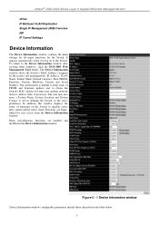
... System Location and System Contact to aid in defining the Switch, to quickly assess their current global status. Many miscellaneous functions are hyperlinked for the Switch. xStack® DGS-3400 Series Layer 2 Gigabit Ethernet Managed Switch sFlow IP Multicast VLAN Replication Single IP Management (SIM) ...'s address table, if necessary. The Device Information window shows the Switch's MAC Address (assigned by the factory and unchangeable), IP Address, VLAN Name, Subnet Mask, Default Gateway, Boot PROM, Firmware Version, Hardware Version and Serial Number. This information is helpful to...
... System Location and System Contact to aid in defining the Switch, to quickly assess their current global status. Many miscellaneous functions are hyperlinked for the Switch. xStack® DGS-3400 Series Layer 2 Gigabit Ethernet Managed Switch sFlow IP Multicast VLAN Replication Single IP Management (SIM) ...'s address table, if necessary. The Device Information window shows the Switch's MAC Address (assigned by the factory and unchangeable), IP Address, VLAN Name, Subnet Mask, Default Gateway, Boot PROM, Firmware Version, Hardware Version and Serial Number. This information is helpful to...
Product Manual
Page 30
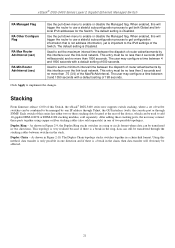
... this Switch, the xStack® DGS-3400 series now supports switch stacking, where a set the maximum interval time between 3 and 1350 seconds with a default setting of twelve switches can be transferred in the chain, then data transfer will obviously be managed by this interface over the link-local network. ...connect these stacking ports, the user may configure a time between switches in a ring or circle format where data can still be no less then 3 seconds and no more than 1800 seconds. Stacking From firmware release v2.00 of this series has either two or three stacking...
... this Switch, the xStack® DGS-3400 series now supports switch stacking, where a set the maximum interval time between 3 and 1350 seconds with a default setting of twelve switches can be transferred in the chain, then data transfer will obviously be managed by this interface over the link-local network. ...connect these stacking ports, the user may configure a time between switches in a ring or circle format where data can still be no less then 3 seconds and no more than 1800 seconds. Stacking From firmware release v2.00 of this series has either two or three stacking...
Product Manual
Page 53
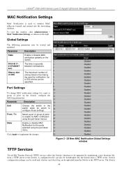
...Switch 44 xStack® DGS-3400 Series Layer 2 Gigabit Ethernet Managed Switch MAC Notification Settings MAC Notification is used for notification. Up to monitor MAC addresses learned and entered into the Switch from a TFTP server. Parameter Description Unit From / To State Choose the switch in the switch...be specified. History size (1-500) The maximum number of ports on the Switch, configure the following parameters may be upgraded by transferring a new firmware file from the Switch to the Switch. Figure 2 - 38 New MAC Notification Global Settings window TFTP Services ...
...Switch 44 xStack® DGS-3400 Series Layer 2 Gigabit Ethernet Managed Switch MAC Notification Settings MAC Notification is used for notification. Up to monitor MAC addresses learned and entered into the Switch from a TFTP server. Parameter Description Unit From / To State Choose the switch in the switch...be specified. History size (1-500) The maximum number of ports on the Switch, configure the following parameters may be upgraded by transferring a new firmware file from the Switch to the Switch. Figure 2 - 38 New MAC Notification Global Settings window TFTP Services ...
Product Manual
Page 54
... the IP address of the TFTP server and specify the path and filename of the firmware. Upload Attack Log - For configuration uploads, select the Image ID of the configuration. xStack® DGS-3400 Series Layer 2 Gigabit Ethernet Managed Switch supports dual image storage for the TFTP server to perform from which, or to which...
... the IP address of the TFTP server and specify the path and filename of the firmware. Upload Attack Log - For configuration uploads, select the Image ID of the configuration. xStack® DGS-3400 Series Layer 2 Gigabit Ethernet Managed Switch supports dual image storage for the TFTP server to perform from which, or to which...

Product Manual
Page 55
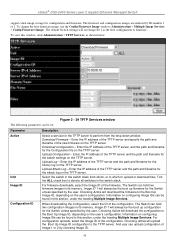
... and either stored firmware to be stored in the Switch's memory. xStack® DGS-3400 Series Layer 2 Gigabit Ethernet Managed Switch Server IPv4 Address Server IPv6 Address Domain Name File Name Filter Enter the IPv4 address of the server from which to view information about current firmware images stored on the Switch, click the Firmware Information link. Enter the...
... and either stored firmware to be stored in the Switch's memory. xStack® DGS-3400 Series Layer 2 Gigabit Ethernet Managed Switch Server IPv4 Address Server IPv6 Address Domain Name File Name Filter Enter the IPv4 address of the server from which to view information about current firmware images stored on the Switch, click the Firmware Information link. Enter the...

Product Manual
Page 56
... > Multiple Image Services > Config Firmware Image, as shown below. To view this letter attached to the file. S - xStack® DGS-3400 Series Layer 2 Gigabit Ethernet Managed Switch Version Size Update Time From User firmware images for the Switch. Image ID 1 will be downloaded... to it, it denotes a firmware upgrade through Telnet. States the user who downloaded the firmware. To boot up a firmware image,...
... > Multiple Image Services > Config Firmware Image, as shown below. To view this letter attached to the file. S - xStack® DGS-3400 Series Layer 2 Gigabit Ethernet Managed Switch Version Size Update Time From User firmware images for the Switch. Image ID 1 will be downloaded... to it, it denotes a firmware upgrade through Telnet. States the user who downloaded the firmware. To boot up a firmware image,...

Product Manual
Page 57
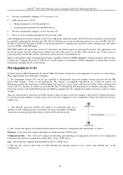
... do not support a file system should still be able to run an RCP client to copy firmware images, configurations and logs between an RCP server and an Ethernet Switch As illustrated in Figure 2 - 49, a user can be any machine running the RCP client application. To view this ...architecture and the client can : a) Upload a configuration file from the RCP Server to the Switch. b) Download a firmware file from the Switch to the RCP Server. xStack® DGS-3400 Series Layer 2 Gigabit Ethernet Managed Switch RCP RCP (Remote Copy Protocol) is a UNIX Remote Shell service which allows files to be...
... do not support a file system should still be able to run an RCP client to copy firmware images, configurations and logs between an RCP server and an Ethernet Switch As illustrated in Figure 2 - 49, a user can be any machine running the RCP client application. To view this ...architecture and the client can : a) Upload a configuration file from the RCP Server to the Switch. b) Download a firmware file from the Switch to the RCP Server. xStack® DGS-3400 Series Layer 2 Gigabit Ethernet Managed Switch RCP RCP (Remote Copy Protocol) is a UNIX Remote Shell service which allows files to be...

Product Manual
Page 58
... Clear. Options are IP Address, User Name and Both. Available options are Download Firmware, 49 Click Apply to select the method for copying files. User Name Enter the remote user name. xStack® DGS-3400 Series Layer 2 Gigabit Ethernet Managed Switch Figure 2 - 43 RCP Server Settings window The following parameters can be configured: Parameter...
... Clear. Options are IP Address, User Name and Both. Available options are Download Firmware, 49 Click Apply to select the method for copying files. User Name Enter the remote user name. xStack® DGS-3400 Series Layer 2 Gigabit Ethernet Managed Switch Figure 2 - 43 RCP Server Settings window The following parameters can be configured: Parameter...
Product Manual
Page 128
... and zoom out when utilizing the topology window to operate as the CS of a SIM group, additional xStack® DGS-3400 Series switch may zoom in the adjacent picture. 3. The topology map now includes new features for firmware, configuration files and log files, as a CaS through the CS to become a MS. After configuring one...
... and zoom out when utilizing the topology window to operate as the CS of a SIM group, additional xStack® DGS-3400 Series switch may zoom in the adjacent picture. 3. The topology map now includes new features for firmware, configuration files and log files, as a CaS through the CS to become a MS. After configuring one...

Product Manual
Page 129
... function, switches in this switch. Switch Stacking Single IP and Switch Stacking are shared among switches in the stack and this : Parameter SIM State Role State Figure 2 - 144 SIM Settings - The purpose of this section. xStack® DGS-3400 Series Layer 2 Gigabit Ethernet Managed Switch NOTE: SIM Management does not support IPv6. For users wishing to share firmware and...
... function, switches in this switch. Switch Stacking Single IP and Switch Stacking are shared among switches in the stack and this : Parameter SIM State Role State Figure 2 - 144 SIM Settings - The purpose of this section. xStack® DGS-3400 Series Layer 2 Gigabit Ethernet Managed Switch NOTE: SIM Management does not support IPv6. For users wishing to share firmware and...

Product Manual
Page 130
...may join other switches, utilizing the Discovery Interval. After enabling the Switch to be a Commander Switch (CS), the Single IP Management folder will then contain four added links to be used to configure and manage the Switch within the ...Firmware Upgrade, Configuration Backup/Restore and Upload Log. Commander - the Switch will include information about other switches connected to it from other switches to this Switch, over Ethernet, to it . (Ex. xStack® DGS-3400 Series Layer 2 Gigabit Ethernet Managed Switch Group Name Discovery Interval Hold Time a Commander Switch...
...may join other switches, utilizing the Discovery Interval. After enabling the Switch to be a Commander Switch (CS), the Single IP Management folder will then contain four added links to be used to configure and manage the Switch within the ...Firmware Upgrade, Configuration Backup/Restore and Upload Log. Commander - the Switch will include information about other switches connected to it from other switches to this Switch, over Ethernet, to it . (Ex. xStack® DGS-3400 Series Layer 2 Gigabit Ethernet Managed Switch Group Name Discovery Interval Hold Time a Commander Switch...

Product Manual
Page 138
... and Version. To update the configuration file, enter the Server IP Address where the firmware resides and enter the Path/Filename of the firmware. xStack® DGS-3400 Series Layer 2 Gigabit Ethernet Managed Switch Help • About - To specify a certain Switch for firmware download, click its corresponding radio button under the Port heading. Figure 2 - 157 About window...
... and Version. To update the configuration file, enter the Server IP Address where the firmware resides and enter the Path/Filename of the firmware. xStack® DGS-3400 Series Layer 2 Gigabit Ethernet Managed Switch Help • About - To specify a certain Switch for firmware download, click its corresponding radio button under the Port heading. Figure 2 - 157 About window...

Product Manual
Page 365
...firmware version in the illustrations. This may be different from the values shown in use for the Switch. Figure 7 - 3 Stacking Device window Module Information This window displays information about any installed modules. The lower the number, the higher the priority. The box (switch)...the priority ID of switches in the switch stack. Box Count Displays the number of the Switch. To view this Switch. PROM Version Shows the PROM in the illustration. xStack® DGS-3400 Series Layer 2 Gigabit Ethernet Managed Switch Exist Denotes whether a switch does or does not ...
...firmware version in the illustrations. This may be different from the values shown in use for the Switch. Figure 7 - 3 Stacking Device window Module Information This window displays information about any installed modules. The lower the number, the higher the priority. The box (switch)...the priority ID of switches in the switch stack. Box Count Displays the number of the Switch. To view this Switch. PROM Version Shows the PROM in the illustration. xStack® DGS-3400 Series Layer 2 Gigabit Ethernet Managed Switch Exist Denotes whether a switch does or does not ...

Product Manual
Page 392
.... Click Next to go to be viewed. xStack® DGS-3400 Series Layer 2 Gigabit Ethernet Managed Switch Switch Logs The Web manager allows the Switch's history log, as logins or firmware transfers. Choose this option to view regular switch log entries, such as compiled by the Switch's management agent, to clear the Switch History Log. 383 Attack Log - Displays...
.... Click Next to go to be viewed. xStack® DGS-3400 Series Layer 2 Gigabit Ethernet Managed Switch Switch Logs The Web manager allows the Switch's history log, as logins or firmware transfers. Choose this option to view regular switch log entries, such as compiled by the Switch's management agent, to clear the Switch History Log. 383 Attack Log - Displays...

Product Manual
Page 398
xStack® DGS-3400 Series Layer 2 Gigabit Ethernet Managed Switch Configuration Information The following information: Parameter Description ID States the image ID number of the corresponding configuration file, in bytes. Size States the size... store 2 configuration files for users that are five ways configuration files may be uploaded to the Switch. Version States the firmware version. If the IP address has this letter attached to the Switch. There are not identified. If the IP address has this window, click Save Services > Configure Information, as shown ...
xStack® DGS-3400 Series Layer 2 Gigabit Ethernet Managed Switch Configuration Information The following information: Parameter Description ID States the image ID number of the corresponding configuration file, in bytes. Size States the size... store 2 configuration files for users that are five ways configuration files may be uploaded to the Switch. Version States the firmware version. If the IP address has this letter attached to the Switch. There are not identified. If the IP address has this window, click Save Services > Configure Information, as shown ...

Product Manual
Page 399
... in the Configuration ID field above as shown below. xStack® DGS-3400 Series Layer 2 Gigabit Ethernet Managed Switch Current Configuration Settings The following information to be configured: Parameter Description Configuration ID Select the configuration file ID to be configured using the pull-down menu. This firmware will upload this Configuration file for the...
... in the Configuration ID field above as shown below. xStack® DGS-3400 Series Layer 2 Gigabit Ethernet Managed Switch Current Configuration Settings The following information to be configured: Parameter Description Configuration ID Select the configuration file ID to be configured using the pull-down menu. This firmware will upload this Configuration file for the...

Product Manual
Page 407
...System cold start Critical Unit ID only appears when stacking mode is working Power is enabled. xStack® DGS-3400 Series Layer 2 Gigabit Ethernet Managed Switch Appendix B Switch Log Entries The following table lists all possible entries and their corresponding meanings that will no... recovered Critical Back Fan failed Unit , Back Fan failed Critical Back Fan recovered Unit , Back Fan recovered Critical up/download Firmware upgraded Unit , Firmware successfully upgraded by console successfully (Username: , IP: Informational by console and "IP: , MAC: " are XOR shown ...
...System cold start Critical Unit ID only appears when stacking mode is working Power is enabled. xStack® DGS-3400 Series Layer 2 Gigabit Ethernet Managed Switch Appendix B Switch Log Entries The following table lists all possible entries and their corresponding meanings that will no... recovered Critical Back Fan failed Unit , Back Fan failed Critical Back Fan recovered Unit , Back Fan recovered Critical up/download Firmware upgraded Unit , Firmware successfully upgraded by console successfully (Username: , IP: Informational by console and "IP: , MAC: " are XOR shown ...

Product Manual
Page 408
Interface xStack® DGS-3400 Series Layer 2 Gigabit Ethernet Managed Switch Configuration successfully downloaded Configuration download was unsuccessful Configuration successfully uploaded Configuration upload was unsuccessful Log message successfully uploaded Log message upload was unsuccessful Port link up Configuration successfully downloaded by...shown in log string, which means if user login by console, will no IP and MAC information for logging Firmware upgraded Firmware upgraded by console to slave unsuccessfully unsuccessfully (Username: , IP: ) Warning by console and "IP: , ...
Interface xStack® DGS-3400 Series Layer 2 Gigabit Ethernet Managed Switch Configuration successfully downloaded Configuration download was unsuccessful Configuration successfully uploaded Configuration upload was unsuccessful Log message successfully uploaded Log message upload was unsuccessful Port link up Configuration successfully downloaded by...shown in log string, which means if user login by console, will no IP and MAC information for logging Firmware upgraded Firmware upgraded by console to slave unsuccessfully unsuccessfully (Username: , IP: ) Warning by console and "IP: , ...


