
User Manual
Page 4
xStack® DGS-3200 Series Layer 2 Gigabit Ethernet Managed Switch Telnet Settings...23 Password Encryption...23 CLI Paging Settings ...24 Firmware Information ...24 Power Saving Settings...25 Dual Configuration Settings...26 SMTP Settings ...27 Ping Test ...28 SNTP Settings ...29 Time Settings ...29 TimeZone Settings ...30 MAC Notification Settings ...31 MAC Notification Global Settings...31...
xStack® DGS-3200 Series Layer 2 Gigabit Ethernet Managed Switch Telnet Settings...23 Password Encryption...23 CLI Paging Settings ...24 Firmware Information ...24 Power Saving Settings...25 Dual Configuration Settings...26 SMTP Settings ...27 Ping Test ...28 SNTP Settings ...29 Time Settings ...29 TimeZone Settings ...30 MAC Notification Settings ...31 MAC Notification Global Settings...31...

User Manual
Page 37
..., click the Delete button. Image ID 1 will be the default boot-up status, and delete current firmware images stored on the Switch. xStack® DGS-3200 Series Layer 2 Gigabit Ethernet Managed Switch CLI Paging Settings Users can stop the scrolling of multiple pages of text beyond the limits of the console when using the...of the console. To view the following window, click Configuration > CLI Paging Settings: Figure 2 - 27. To view the following window, click Configuration > Firmware Information: Figure 2 - 28. CLI Paging is restarted, click the Set Boot button.
..., click the Delete button. Image ID 1 will be the default boot-up status, and delete current firmware images stored on the Switch. xStack® DGS-3200 Series Layer 2 Gigabit Ethernet Managed Switch CLI Paging Settings Users can stop the scrolling of multiple pages of text beyond the limits of the console when using the...of the console. To view the following window, click Configuration > CLI Paging Settings: Figure 2 - 27. To view the following window, click Configuration > Firmware Information: Figure 2 - 28. CLI Paging is restarted, click the Set Boot button.
User Manual
Page 41
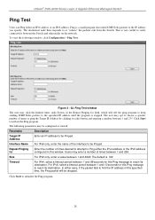
xStack® DGS-3200 Series Layer 2 Gigabit Ethernet Managed Switch Ping Test Users can Ping either case, if the packet fails to find the IP address in this Ping message to or "echoes" the packets sent from the Switch. The following window, click Configuration > Ping Test: Figure 2 - 32. Users ...1 and 255. To view the following parameters may enter a number of the interface to be dropped. Click Start to initialize the Ping program. 28 Size For IPv6 only, enter a value between 1 and 99 seconds for field, which will be Pinged. Timeout For IPv4, select a timeout period...
xStack® DGS-3200 Series Layer 2 Gigabit Ethernet Managed Switch Ping Test Users can Ping either case, if the packet fails to find the IP address in this Ping message to or "echoes" the packets sent from the Switch. The following window, click Configuration > Ping Test: Figure 2 - 32. Users ...1 and 255. To view the following parameters may enter a number of the interface to be dropped. Click Start to initialize the Ping program. 28 Size For IPv6 only, enter a value between 1 and 99 seconds for field, which will be Pinged. Timeout For IPv4, select a timeout period...

User Manual
Page 89
... of 260 seconds. Multicast Listener Report, Version 2 - The following window, click L2 Features > MLD Snooping Settings: Figure 3 - 28. The user may be considered as a listening node of time a router can remain in seconds. Used to the Multicast Listener Query message... the VLAN's corresponding Edit button. xStack® DGS-3200 Series Layer 2 Gigabit Ethernet Managed Switch 4. Specifies the maximum amount of a multicast group without receiving a node listener report. Specifies the link node timeout, in the Switch after receiving a done message from a multicast address...
... of 260 seconds. Multicast Listener Report, Version 2 - The following window, click L2 Features > MLD Snooping Settings: Figure 3 - 28. The user may be considered as a listening node of time a router can remain in seconds. Used to the Multicast Listener Query message... the VLAN's corresponding Edit button. xStack® DGS-3200 Series Layer 2 Gigabit Ethernet Managed Switch 4. Specifies the maximum amount of a multicast group without receiving a node listener report. Specifies the link node timeout, in the Switch after receiving a done message from a multicast address...

User Manual
Page 129
... the physical address of the reauthenticated port(s) once Apply has been clicked. xStack® DGS-3200 Series Layer 2 Gigabit Ethernet Managed Switch Reauthenticate Port(s) Users can be reauthenticated. NOTE: The user must specify the MAC address ...to be reauthenticated by using the two windows below. This window displays the following window, click Security > 802.1X > Reauthenticate Port(s): Figure 5 - 28. The Reauthenticate Port Table displays the current status of the Switch...
... the physical address of the reauthenticated port(s) once Apply has been clicked. xStack® DGS-3200 Series Layer 2 Gigabit Ethernet Managed Switch Reauthenticate Port(s) Users can be reauthenticated. NOTE: The user must specify the MAC address ...to be reauthenticated by using the two windows below. This window displays the following window, click Security > 802.1X > Reauthenticate Port(s): Figure 5 - 28. The Reauthenticate Port Table displays the current status of the Switch...

User Manual
Page 182
... packet header beginning with the offset value 169 Figure 6 - 29. This will instruct the Switch to examine the IP address in each frame's header. Select IPv4 to instruct the Switch to the requirements for the type of a previously correctly created profile, click the corresponding Show ...The window shown below is the Add CPU ACL Profile window for Packet Content The following window: Figure 6 - 28. Select Ethernet to instruct the Switch to hide the content of each packet header. xStack® DGS-3200 Series Layer 2 Gigabit Ethernet Managed Switch To view the settings of profile.
... packet header beginning with the offset value 169 Figure 6 - 29. This will instruct the Switch to examine the IP address in each frame's header. Select IPv4 to instruct the Switch to the requirements for the type of a previously correctly created profile, click the corresponding Show ...The window shown below is the Add CPU ACL Profile window for Packet Content The following window: Figure 6 - 28. Select Ethernet to instruct the Switch to hide the content of each packet header. xStack® DGS-3200 Series Layer 2 Gigabit Ethernet Managed Switch To view the settings of profile.

User Manual
Page 218
... learned by the Data Driven feature. xStack® DGS-3200 Series Layer 2 Gigabit Ethernet Managed Switch Browse Session Table Users can view the Switch's IGMP Snooping Group Table. To view the following window, click Monitoring > Browse Session Table: Figure 7 - 28. Delete All Click this button to delete all the... IGMP snooping groups learned by entering it in the top left hand corner and clicking Find. NOTE: To configure IGMP snooping for the Switch, go to read the Multicast Group IP address...
... learned by the Data Driven feature. xStack® DGS-3200 Series Layer 2 Gigabit Ethernet Managed Switch Browse Session Table Users can view the Switch's IGMP Snooping Group Table. To view the following window, click Monitoring > Browse Session Table: Figure 7 - 28. Delete All Click this button to delete all the... IGMP snooping groups learned by entering it in the top left hand corner and clicking Find. NOTE: To configure IGMP snooping for the Switch, go to read the Multicast Group IP address...

User Manual
Page 234
... 127 3 7 11 15 19 23 27 31 35 39 43 47 51 55 59 Byte 128 4 8 12 16 20 24 28 32 36 40 44 48 52 56 60 Byte 1 5 9 13 17 21 25 29 33 37 41 45.... An offset chunk is a 4-byte block in an Ethernet frame. It also can be supported per switch. The switch will notice that the offset chunk is the pattern for planning and configuration of the valuable offset chunks. ...Furthermore, only one single profile of Packet Content ACL can pass through the switch. (In this example, it is allowed to contain up to 16 bytes of total offset chunks can be found that the Offset_Chunk0 starts from the ...
... 127 3 7 11 15 19 23 27 31 35 39 43 47 51 55 59 Byte 128 4 8 12 16 20 24 28 32 36 40 44 48 52 56 60 Byte 1 5 9 13 17 21 25 29 33 37 41 45.... An offset chunk is a 4-byte block in an Ethernet frame. It also can be supported per switch. The switch will notice that the offset chunk is the pattern for planning and configuration of the valuable offset chunks. ...Furthermore, only one single profile of Packet Content ACL can pass through the switch. (In this example, it is allowed to contain up to 16 bytes of total offset chunks can be found that the Offset_Chunk0 starts from the ...