Reference Guide
Page 2
... IP Information ...18 Password...18 i Table of Contents D-Link Web Smart Switch User Manual Table of Contents Table of Contents ...i About This Guide...1 Terms/Usage...1 Copyright and Trademarks ...1 1 Product Introduction ...2 DGS-1210-20 ...3 Front Panel ...3 Rear Panel...3 DGS-1210-28 ...3 Front Panel ...3 Rear Panel...4 DGS-1210-28P...4 Front Panel ...4 Rear Panel...4 DGS-1210-52 ...5 Front Panel ...5 Rear Panel...5 2 Hardware Installation ...6 Step...
... IP Information ...18 Password...18 i Table of Contents D-Link Web Smart Switch User Manual Table of Contents Table of Contents ...i About This Guide...1 Terms/Usage...1 Copyright and Trademarks ...1 1 Product Introduction ...2 DGS-1210-20 ...3 Front Panel ...3 Rear Panel...3 DGS-1210-28 ...3 Front Panel ...3 Rear Panel...4 DGS-1210-28P...4 Front Panel ...4 Rear Panel...4 DGS-1210-52 ...5 Front Panel ...5 Rear Panel...5 2 Hardware Installation ...6 Step...

Reference Guide
Page 3
Table of Contents D-Link Web Smart Switch User Manual SNMP ...19 Web-based Management...21 Tool Bar > Save Menu ...22 Save Configuration ...22 Save Log ...22 Tool Bar > Tool Menu ...22 Reset ...22 Reset ... > Dynamic Forwarding Table 37 L2 Functions > Spanning Tree > STP Global Settings 37 L2 Functions > Spanning Tree > STP Port Settings 38 L2 Functions > Link Aggregation > Port Trunking 39 L2 Functions > Link Aggregation > LACP Port Settings 40 L2 Functions > Multicast > IGMP Snooping 40 L2 Functions > Multicast > Multicast Forwarding 42 L2 Functions > Multicast > Multicast Filtering...
Table of Contents D-Link Web Smart Switch User Manual SNMP ...19 Web-based Management...21 Tool Bar > Save Menu ...22 Save Configuration ...22 Save Log ...22 Tool Bar > Tool Menu ...22 Reset ...22 Reset ... > Dynamic Forwarding Table 37 L2 Functions > Spanning Tree > STP Global Settings 37 L2 Functions > Spanning Tree > STP Port Settings 38 L2 Functions > Link Aggregation > Port Trunking 39 L2 Functions > Link Aggregation > LACP Port Settings 40 L2 Functions > Multicast > IGMP Snooping 40 L2 Functions > Multicast > Multicast Forwarding 42 L2 Functions > Multicast > Multicast Filtering...
Reference Guide
Page 4
...86 iii Ethernet Technology...85 Gigabit Ethernet Technology ...85 Fast Ethernet Technology...85 Switching Technology ...85 Appendix B - Table of Contents D-Link Web Smart Switch User Manual L2 Functions > LLDP > LLDP Management Address Table 48 L2 Functions > LLDP > LLDP Local Port Table 48 L2 Functions > ... ...59 ACL > ACL Wizard ...61 ACL > ACL Profile List...62 ACL > ACL Finder ...65 PoE > PoE Global Settings (DGS-1210-28P only 65 PoE > PoE Port Settings (DGS-1210-28P only 66 SNMP > Trap to SmartConsole Utility...67 SNMP > SNMP > SNMP Global Settings 67 SNMP > SNMP > SNMP User ...68...
...86 iii Ethernet Technology...85 Gigabit Ethernet Technology ...85 Fast Ethernet Technology...85 Switching Technology ...85 Appendix B - Table of Contents D-Link Web Smart Switch User Manual L2 Functions > LLDP > LLDP Management Address Table 48 L2 Functions > LLDP > LLDP Local Port Table 48 L2 Functions > ... ...59 ACL > ACL Wizard ...61 ACL > ACL Profile List...62 ACL > ACL Finder ...65 PoE > PoE Global Settings (DGS-1210-28P only 65 PoE > PoE Port Settings (DGS-1210-28P only 66 SNMP > Trap to SmartConsole Utility...67 SNMP > SNMP > SNMP Global Settings 67 SNMP > SNMP > SNMP User ...68...

Reference Guide
Page 5
Table of Contents D-Link Web Smart Switch User Manual Hardware Specifications ...86 Key Components / Performance ...86 Port Functions ...86 Physical & Environment ...86 Emission (EMI) Certifications ...86 Safety Certifications...86 Features ...86 L2 Features ...86 D-Link Green Technology ...87 VLAN ...87 QoS (Quality of Service)...87 Security...87 Management...87 Appendix C - Rack mount Instructions ...88 iv
Table of Contents D-Link Web Smart Switch User Manual Hardware Specifications ...86 Key Components / Performance ...86 Port Functions ...86 Physical & Environment ...86 Emission (EMI) Certifications ...86 Safety Certifications...86 Features ...86 L2 Features ...86 D-Link Green Technology ...87 VLAN ...87 QoS (Quality of Service)...87 Security...87 Management...87 Appendix C - Rack mount Instructions ...88 iv
Reference Guide
Page 6
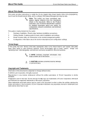
.... Other trademarks and trade names may appear slightly different from the illustrations shown in this text: D-Link and the D-LINK logo are trademarks of D-Link Corporation; Refer to the Product Instruction and Technical Specification sections for detailed information about the function descriptions ...in trademarks and trade names other Ethernet switches. About This Guide D-Link Web Smart Switch User Manual About This Guide This guide provides instructions to install the D-Link Gigabit Web Smart Switch DGS-1210-20/28/28P/52, how to use of the device. Getting Started: A ...
.... Other trademarks and trade names may appear slightly different from the illustrations shown in this text: D-Link and the D-LINK logo are trademarks of D-Link Corporation; Refer to the Product Instruction and Technical Specification sections for detailed information about the function descriptions ...in trademarks and trade names other Ethernet switches. About This Guide D-Link Web Smart Switch User Manual About This Guide This guide provides instructions to install the D-Link Gigabit Web Smart Switch DGS-1210-20/28/28P/52, how to use of the device. Getting Started: A ...
Reference Guide
Page 7
1 Product Introduction D-Link Web Smart Switch User Manual 1 Product Introduction Thank you and congratulations on your purchase of shared resources, such as server or gateway devices. All models are displayed on DGS-1210 series such as a password change the IP address of the PC and...change or firmware upgrade. The first 4 ports of DGS-1210-28P also support up to -view front panel diagnostic LEDs, and provides advanced features including network security, traffic segmentation, QoS and versatile management. D-Link Green Technology. These functions allow switches to work seamlessly...
1 Product Introduction D-Link Web Smart Switch User Manual 1 Product Introduction Thank you and congratulations on your purchase of shared resources, such as server or gateway devices. All models are displayed on DGS-1210 series such as a password change the IP address of the PC and...change or firmware upgrade. The first 4 ports of DGS-1210-28P also support up to -view front panel diagnostic LEDs, and provides advanced features including network security, traffic segmentation, QoS and versatile management. D-Link Green Technology. These functions allow switches to work seamlessly...

Reference Guide
Page 8
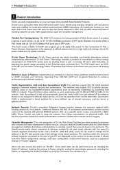
... port is running on 1000M. DGS-1210-20 16-Port 10/100/1000Mbps plus 4 1000Base-T/SFP Slot Web Smart Switch. Port Link/Act/Speed LED (1-16, 17F, 18F, 19F, 20F): The Link/Act/Speed LED flashes, which indicates a network link through the corresponding port. 1 Product Introduction D-Link Web Smart Switch User Manual In addition, users can utilize...
... port is running on 1000M. DGS-1210-20 16-Port 10/100/1000Mbps plus 4 1000Base-T/SFP Slot Web Smart Switch. Port Link/Act/Speed LED (1-16, 17F, 18F, 19F, 20F): The Link/Act/Speed LED flashes, which indicates a network link through the corresponding port. 1 Product Introduction D-Link Web Smart Switch User Manual In addition, users can utilize...
Reference Guide
Page 9
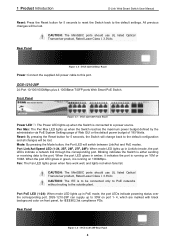
...DGS-1210-28P can supply up in green, it indicates the port is either sending or receiving data to be lost . Front Panel Figure 1.5 - When the port LED glows in PoE mode, the port LEDs indicate powering status over the corresponding port. 1 Product Introduction D-Link Web Smart Switch User Manual... without routing to the outside plant. All previous changes will switch between Link/Act and PoE modes. Rear Panel Figure 1.4 - DGS-1210-28P 24-Port 10/100/1000Mbps plus 4 1000Base-T/SFP ports Web Smart PoE Switch. Port Link/Act/Speed LED (1-24, 25F, 26F, 27F, 28F): When mode...
...DGS-1210-28P can supply up in green, it indicates the port is either sending or receiving data to be lost . Front Panel Figure 1.5 - When the port LED glows in PoE mode, the port LEDs indicate powering status over the corresponding port. 1 Product Introduction D-Link Web Smart Switch User Manual... without routing to the outside plant. All previous changes will switch between Link/Act and PoE modes. Rear Panel Figure 1.4 - DGS-1210-28P 24-Port 10/100/1000Mbps plus 4 1000Base-T/SFP ports Web Smart PoE Switch. Port Link/Act/Speed LED (1-24, 25F, 26F, 27F, 28F): When mode...
Reference Guide
Page 10
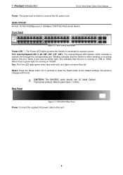
... data to the port. Reset: Press the Reset button for 5 seconds to reset the Switch back to the default settings. DGS-1210-52 Rear Panel Power: Connect the supplied AC power cable to this indicates that the Switch is running on 1000M. Rear Panel Figure... UL listed Optical Transceiver product, Rated Laser Class I. 3.3Vdc. Port Link/Act/Speed LED (1-48, 49F, 50F, 51F, 52F): The Link/Act/Speed LED flashes, which indicates a network link through the corresponding port. 1 Product Introduction D-Link Web Smart Switch User Manual Power: The power port is connected to a power source.
... data to the port. Reset: Press the Reset button for 5 seconds to reset the Switch back to the default settings. DGS-1210-52 Rear Panel Power: Connect the supplied AC power cable to this indicates that the Switch is running on 1000M. Rear Panel Figure... UL listed Optical Transceiver product, Rated Laser Class I. 3.3Vdc. Port Link/Act/Speed LED (1-48, 49F, 50F, 51F, 52F): The Link/Act/Speed LED flashes, which indicates a network link through the corresponding port. 1 Product Introduction D-Link Web Smart Switch User Manual Power: The power port is connected to a power source.

Reference Guide
Page 11
Please consult the packing list located in the User Manual to the bottom Rack Installation The switch can be mounted in a wiring closet with other equipment. One D-Link Web-Smart Switch One AC power cord Four rubber feet Screws and two mounting brackets ... attach the mounting brackets to the switch's side panels (one on each corner of the device's base. 2 Hardware Installation D-Link Web Smart Switch User Manual 2 Hardware Installation This chapter provides unpacking and installation information for replacement. Step 2: Switch Installation For safe switch installation and operation...
Please consult the packing list located in the User Manual to the bottom Rack Installation The switch can be mounted in a wiring closet with other equipment. One D-Link Web-Smart Switch One AC power cord Four rubber feet Screws and two mounting brackets ... attach the mounting brackets to the switch's side panels (one on each corner of the device's base. 2 Hardware Installation D-Link Web Smart Switch User Manual 2 Hardware Installation This chapter provides unpacking and installation information for replacement. Step 2: Switch Installation For safe switch installation and operation...

Reference Guide
Page 12
2 Hardware Installation D-Link Web Smart Switch User Manual Then, use of equipment nameplate ratings should be used when addressing this concern. Appropriate consideration of power strips)." use the screws provided with the maximum ...
2 Hardware Installation D-Link Web Smart Switch User Manual Then, use of equipment nameplate ratings should be used when addressing this concern. Appropriate consideration of power strips)." use the screws provided with the maximum ...

Reference Guide
Page 13
When power is resumed, plug the switch back in case of power failure. 2 Hardware Installation D-Link Web Smart Switch User Manual Power Failure As a precaution, the switch should be unplugged in . 8
When power is resumed, plug the switch back in case of power failure. 2 Hardware Installation D-Link Web Smart Switch User Manual Power Failure As a precaution, the switch should be unplugged in . 8

Reference Guide
Page 14
...Ethernet connection 2. Please refer to the Ethernet port on the front panel of your PC and it is easier to manage multiple D-Link Web Smart Switches, the SmartConsole Utility is used for the Web-based Management and the SmartConsole Utility. Connected Ethernet cable 9 A ... SmartConsole Utility, you want to initialize multiple Smart Switches. 3 Getting Started D-Link Web Smart Switch User Manual 3 Getting Started This chapter introduces the management interface of your device: 1. Management Options The D-Link Web Smart Switch can be assigned its own IP Address, which is a ...
...Ethernet connection 2. Please refer to the Ethernet port on the front panel of your PC and it is easier to manage multiple D-Link Web Smart Switches, the SmartConsole Utility is used for the Web-based Management and the SmartConsole Utility. Connected Ethernet cable 9 A ... SmartConsole Utility, you want to initialize multiple Smart Switches. 3 Getting Started D-Link Web Smart Switch User Manual 3 Getting Started This chapter introduces the management interface of your device: 1. Management Options The D-Link Web Smart Switch can be assigned its own IP Address, which is a ...

Reference Guide
Page 15
... running Windows 7, Vista, XP, or 2000 on the installation CD and the other is manual installation. 10 The web configuration can also be accessed through essential settings of the D-Link Web Smart Switch. The switch supports 10 languages including English, Traditional Chinese, Simplified Chinese, German... Box Smart Wizard After a successful login, the Smart Wizard will enter the Web-based Management interface. 3 Getting Started D-Link Web Smart Switch User Manual Login Web-based Management In order to login and configure the switch via an Ethernet connection, the PC must have an...
... running Windows 7, Vista, XP, or 2000 on the installation CD and the other is manual installation. 10 The web configuration can also be accessed through essential settings of the D-Link Web Smart Switch. The switch supports 10 languages including English, Traditional Chinese, Simplified Chinese, German... Box Smart Wizard After a successful login, the Smart Wizard will enter the Web-based Management interface. 3 Getting Started D-Link Web Smart Switch User Manual Login Web-based Management In order to login and configure the switch via an Ethernet connection, the PC must have an...

Reference Guide
Page 16
3 Getting Started D-Link Web Smart Switch User Manual NOTE: Please be sure to uninstall any existing SmartConsole Utility from your CD-Rom/DVD-Rom Drive to start the autorun menu, or right click ... on -screen instructions to the same L2 network segment of your CD-Rom/DVD-Rom Drive. 2. Connect the Smart Switch to install the SmartConsole Utility manually. 1. For detailed explanations of SmartConsole's functions, please refer to discover the Smart Switches. Option 1: Follow these steps to the same L2 network segment of your...
3 Getting Started D-Link Web Smart Switch User Manual NOTE: Please be sure to uninstall any existing SmartConsole Utility from your CD-Rom/DVD-Rom Drive to start the autorun menu, or right click ... on -screen instructions to the same L2 network segment of your CD-Rom/DVD-Rom Drive. 2. Connect the Smart Switch to install the SmartConsole Utility manually. 1. For detailed explanations of SmartConsole's functions, please refer to discover the Smart Switches. Option 1: Follow these steps to the same L2 network segment of your...

Reference Guide
Page 17
...to show the events of the switch. Click View Log to launch the Log window. Click Clear Log to clear all D-Link smart switches, which were selected as the main body, and SmartConsole Settings at the left . Click OK to basic configurations of... the SmartConsole Utility and the device. Figure 4.2 - 4 SmartConsole Utility D-Link Web Smart Switch User Manual 4 SmartConsole Utility The D-Link SmartConsole Utility allows the administrator to quickly discover all log entries. SmartConsole Utility SmartConsole Settings The SmartConsole Settings at the...
...to show the events of the switch. Click View Log to launch the Log window. Click Clear Log to clear all D-Link smart switches, which were selected as the main body, and SmartConsole Settings at the left . Click OK to basic configurations of... the SmartConsole Utility and the device. Figure 4.2 - 4 SmartConsole Utility D-Link Web Smart Switch User Manual 4 SmartConsole Utility The D-Link SmartConsole Utility allows the administrator to quickly discover all log entries. SmartConsole Utility SmartConsole Settings The SmartConsole Settings at the...

Reference Guide
Page 18
... SmartConsole Utility and the device. Date/Time indicates when the trap message was received File By clicking on this trap message. 4 SmartConsole Utility D-Link Web Smart Switch User Manual Figure 4.3 - SmartConsole File 13 SmartConsole Log Trap Click this icon to exit Figure 4.4 - Click Clear Trap to show the events of this icon...
... SmartConsole Utility and the device. Date/Time indicates when the trap message was received File By clicking on this trap message. 4 SmartConsole Utility D-Link Web Smart Switch User Manual Figure 4.3 - SmartConsole File 13 SmartConsole Log Trap Click this icon to exit Figure 4.4 - Click Clear Trap to show the events of this icon...

Reference Guide
Page 19
4 SmartConsole Utility D-Link Web Smart Switch User Manual Monitor Save: Records the setting of the Device List in an appointed filename and file path. To apply the configuration, insert the correct device password ... Product Name, IP Address, Gateway, Subnet Mask, System Name, Location, Trap Host IP, Switch Group Interval, and DHCP Client Setting of the Switch. Monitor Load: Manually load a Device List setting file. SmartConsole Help Device Configuration The Device Configuration in the Confirm Password box and then click OK 14
4 SmartConsole Utility D-Link Web Smart Switch User Manual Monitor Save: Records the setting of the Device List in an appointed filename and file path. To apply the configuration, insert the correct device password ... Product Name, IP Address, Gateway, Subnet Mask, System Name, Location, Trap Host IP, Switch Group Interval, and DHCP Client Setting of the Switch. Monitor Load: Manually load a Device List setting file. SmartConsole Help Device Configuration The Device Configuration in the Confirm Password box and then click OK 14

Reference Guide
Page 20
4 SmartConsole Utility D-Link Web Smart Switch User Manual Figure 4.7 - Figure 4.8 - Click on this icon to launch the Firmware Upgrade window. Specify the Firmware Path (or Browse for any reason. SmartConsole Device Settings Device ...
4 SmartConsole Utility D-Link Web Smart Switch User Manual Figure 4.7 - Figure 4.8 - Click on this icon to launch the Firmware Upgrade window. Specify the Firmware Path (or Browse for any reason. SmartConsole Device Settings Device ...

Reference Guide
Page 21
... the Web-based Management by double-clicking the device in the Device List shows the default IP is still used, it . 4 SmartConsole Utility D-Link Web Smart Switch User Manual CAUTION: Do not disconnect the PC or remove the power cord from the DHCP server. The device will renew the IP address from...
... the Web-based Management by double-clicking the device in the Device List shows the default IP is still used, it . 4 SmartConsole Utility D-Link Web Smart Switch User Manual CAUTION: Do not disconnect the PC or remove the power cord from the DHCP server. The device will renew the IP address from...


