
Product Manual
Page 2
......19 SNMP Settings ...20 System Settings...21 Web-based Management...22 Tool Bar > Save Menu ...23 i Table of Contents D-Link Web Smart Switch User Manual Table of Contents Table of Contents ...i About This Guide...1 Terms/Usage...1 Copyright and Trademarks ...1 Product Introduction ...2 DGS-1210-16 ...3 Front Panel ...3 Rear Panel...3 DGS-1210-24 ...3 Front Panel ...3 Rear Panel...4 DGS-1210-48 ...4 Front...
......19 SNMP Settings ...20 System Settings...21 Web-based Management...22 Tool Bar > Save Menu ...23 i Table of Contents D-Link Web Smart Switch User Manual Table of Contents Table of Contents ...i About This Guide...1 Terms/Usage...1 Copyright and Trademarks ...1 Product Introduction ...2 DGS-1210-16 ...3 Front Panel ...3 Rear Panel...3 DGS-1210-24 ...3 Front Panel ...3 Rear Panel...4 DGS-1210-48 ...4 Front...
Product Manual
Page 7
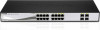
.... NOTE: On DGS-1210-16, the SFP ports are shared with normal RJ-45 ports 13 to connect the AC power cord. DGS-1210-24 Front Panel SFP ports for optical transceivers Power LED : The Power LED lights up when the Switch is either 3 Port Link/Act/Speed LED (1-20, 21F, 22F,... 23F, 24F, 21T, 22T, 23T, 24T): The Link/Act/Speed LED flashes, which indicates a network link through the corresponding port. DGS-1210-16 Front Panel SFP ports for optical transceivers Power LED : The Power...
.... NOTE: On DGS-1210-16, the SFP ports are shared with normal RJ-45 ports 13 to connect the AC power cord. DGS-1210-24 Front Panel SFP ports for optical transceivers Power LED : The Power LED lights up when the Switch is either 3 Port Link/Act/Speed LED (1-20, 21F, 22F,... 23F, 24F, 21T, 22T, 23T, 24T): The Link/Act/Speed LED flashes, which indicates a network link through the corresponding port. DGS-1210-16 Front Panel SFP ports for optical transceivers Power LED : The Power...
Product Manual
Page 19
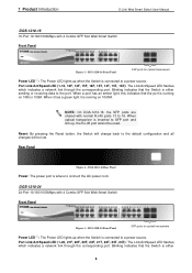
SmartConsole Device Settings 15 4 SmartConsole Utility D-Link Web Smart Switch User Manual Device Configuration The Device Configuration in the Confirm Password box and then click OK Figure 20 - Here you can configure the Product Name, IP Address, Gateway, Subnet Mask, System Name, Location, Trap Host IP, Switch Group Interval, and DHCP Client Setting...
SmartConsole Device Settings 15 4 SmartConsole Utility D-Link Web Smart Switch User Manual Device Configuration The Device Configuration in the Confirm Password box and then click OK Figure 20 - Here you can configure the Product Name, IP Address, Gateway, Subnet Mask, System Name, Location, Trap Host IP, Switch Group Interval, and DHCP Client Setting...

Product Manual
Page 24
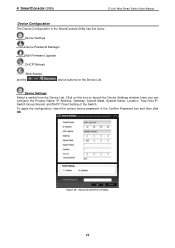
For the complete SNMP function, please check "Setup Menu > System > SNMP Settings" in Smart Wizard 20 Click Enabled, enter Community names, and then click Apply to retrieve MIB objects values. Default Community name is Disabled. Read_Only Community: Read-only...authorized management stations to quickly enable/disable the SNMP function and configure the SNMP community name. The default SNMP Setting is public. 5 Configuration D-Link Web Smart Switch User Manual SNMP Settings The SNMP Setting allows you to retrieve and modify MIB object values. Default Community name is private.
For the complete SNMP function, please check "Setup Menu > System > SNMP Settings" in Smart Wizard 20 Click Enabled, enter Community names, and then click Apply to retrieve MIB objects values. Default Community name is Disabled. Read_Only Community: Read-only...authorized management stations to quickly enable/disable the SNMP function and configure the SNMP community name. The default SNMP Setting is public. 5 Configuration D-Link Web Smart Switch User Manual SNMP Settings The SNMP Setting allows you to retrieve and modify MIB object values. Default Community name is private.
Product Manual
Page 38
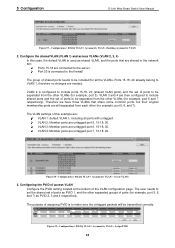
... Configuration D-Link Web Smart Switch User Manual Figure 57 - VLAN 3 and 4 are connected to the server Port 20 is configured to include ports 15-18, 20 (shared VLAN ports) and the set of ports to be included for example, port 5). VLAN 3: Member ports are untagged port 7, 15-18, 20. Create VLANs...but their original membership ports are : VLAN 1: default VLAN 1, including all the VLANs. VLAN 4: Member ports are untagged port 6, 15-18, 20. Figure 59 - Figure 58 - Therefore we have three VLANs that are shared in the network are: Ports 15-18 are then configured to be...
... Configuration D-Link Web Smart Switch User Manual Figure 57 - VLAN 3 and 4 are connected to the server Port 20 is configured to include ports 15-18, 20 (shared VLAN ports) and the set of ports to be included for example, port 5). VLAN 3: Member ports are untagged port 7, 15-18, 20. Create VLANs...but their original membership ports are : VLAN 1: default VLAN 1, including all the VLANs. VLAN 4: Member ports are untagged port 6, 15-18, 20. Figure 59 - Figure 58 - Therefore we have three VLANs that are shared in the network are: Ports 15-18 are then configured to be...
Product Manual
Page 44
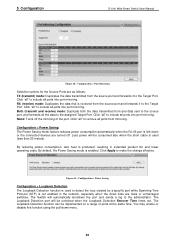
...life and lower operating costs. Configuration > Power Saving Configuration > Loopback Detection The Loopback Detection function is used (less than 20 meters). Configuration > Port Mirroring Selection options for the Source Ports are hubs or unmanaged switches. RX (receive) mode: Duplicates the data ... the loop created by a specific port while Spanning Tree Protocol (STP) is produced, resulting in the network, especially when the down links are as follows: TX (transmit) mode: Duplicates the data transmitted from the source port and forwards it to the administrator. Both (...
...life and lower operating costs. Configuration > Power Saving Configuration > Loopback Detection The Loopback Detection function is used (less than 20 meters). Configuration > Port Mirroring Selection options for the Source Ports are hubs or unmanaged switches. RX (receive) mode: Duplicates the data ... the loop created by a specific port while Spanning Tree Protocol (STP) is produced, resulting in the network, especially when the down links are as follows: TX (transmit) mode: Duplicates the data transmitted from the source port and forwards it to the administrator. Both (...

Product Manual
Page 47
... Delay of the settings configured for forwarding packets: the lower the value, the higher the priority. Root port: Displays the root port. 5 Configuration D-Link Web Smart Switch User Manual RSTP can operate with other switches for RSTP. Most of the Root Bridge. Configuration > Spanning Tree > STP Global Settings... 802.1D STP standard. By default, Rapid Spanning Tree is 6. TX Hold Count (1-10): Used to set the time interval between bridges is 20. (Max Age has to renew the page. 43 The default is disabled. Root Bridge: Displays the MAC address of the Root Bridge. BPDU ...
... Delay of the settings configured for forwarding packets: the lower the value, the higher the priority. Root port: Displays the root port. 5 Configuration D-Link Web Smart Switch User Manual RSTP can operate with other switches for RSTP. Most of the Root Bridge. Configuration > Spanning Tree > STP Global Settings... 802.1D STP standard. By default, Rapid Spanning Tree is 6. TX Hold Count (1-10): Used to set the time interval between bridges is 20. (Max Age has to renew the page. 43 The default is disabled. Root Bridge: Displays the MAC address of the Root Bridge. BPDU ...
