Reference Guide
Page 7
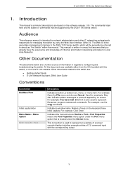
... that is used to configuring and troubleshooting the switch. For example: Click Enter. The Web UI is also used to this manual. For example: use the copy command. D-Link DGS-1100 Series Switch User Manual 1. May also indicate system messages or prompts appearing on the software release 1.00. Indicates a window name. Device > Port > Port Properties...
... that is used to configuring and troubleshooting the switch. For example: Click Enter. The Web UI is also used to this manual. For example: use the copy command. D-Link DGS-1100 Series Switch User Manual 1. May also indicate system messages or prompts appearing on the software release 1.00. Indicates a window name. Device > Port > Port Properties...
Reference Guide
Page 8
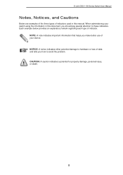
... attention to these indicators. CAUTION: A caution indicates a potential for property damage, personal injury, or death. 2 D-Link DGS-1100 Series Switch User Manual Notes, Notices, and Cautions Below are examples of the three types of indicators used in this manual. Each example below provides an explanatory remark regarding each type of data and tells you how...
... attention to these indicators. CAUTION: A caution indicates a potential for property damage, personal injury, or death. 2 D-Link DGS-1100 Series Switch User Manual Notes, Notices, and Cautions Below are examples of the three types of indicators used in this manual. Each example below provides an explanatory remark regarding each type of data and tells you how...
Reference Guide
Page 9
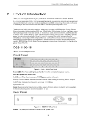
...to connect the AC power cord. 3 The brand-new DGS-1100 series are housed in a short period of time, ports on your purchase of D-Link DGS-1100 Series Switch Products. While connecting to a power source. DGS-1100-16 Rear Panel Power: The power port is connected to... (SMB) networking. Rear Panel Figure 2-2 - Link/Act/Speed LED (Ports 1-16): Solid Green: When there is received, the switch wakes and works immediately. D-Link DGS-1100 Series Switch User Manual 2. Product Introduction Thank you and congratulations on DGS-1100 switch get into power saving mode automatically.
...to connect the AC power cord. 3 The brand-new DGS-1100 series are housed in a short period of time, ports on your purchase of D-Link DGS-1100 Series Switch Products. While connecting to a power source. DGS-1100-16 Rear Panel Power: The power port is connected to... (SMB) networking. Rear Panel Figure 2-2 - Link/Act/Speed LED (Ports 1-16): Solid Green: When there is received, the switch wakes and works immediately. D-Link DGS-1100 Series Switch User Manual 2. Product Introduction Thank you and congratulations on DGS-1100 switch get into power saving mode automatically.

Reference Guide
Page 10
... Indicates that the port is running at the port. Blinking Green: There is either sending or receiving data to a power source. DGS-1100-18 Rear Panel Power: The power port is connected to the port. Solid Amber: Indicates that the Switch is reception or transmission ... 17-18): Solid Green: There is a secure 1000Mbps connection at the port. Rear Panel Figure 2-4 - Light off : No link. Light off : No link. D-Link DGS-1100 Series Switch User Manual DGS-1100-18 16-Port 10/100/1000Mpbs + 2 Port SFP 1000 Mbps Switch Front Panel Figure 2-3 - Reset: By pressing the Reset ...
... Indicates that the port is running at the port. Blinking Green: There is either sending or receiving data to a power source. DGS-1100-18 Rear Panel Power: The power port is connected to the port. Solid Amber: Indicates that the Switch is reception or transmission ... 17-18): Solid Green: There is a secure 1000Mbps connection at the port. Rear Panel Figure 2-4 - Light off : No link. Light off : No link. D-Link DGS-1100 Series Switch User Manual DGS-1100-18 16-Port 10/100/1000Mpbs + 2 Port SFP 1000 Mbps Switch Front Panel Figure 2-3 - Reset: By pressing the Reset ...
Reference Guide
Page 11
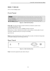
...Switch Front Panel D-Link DGS-1100 Series Switch User Manual Figure 2-5 - Rear Panel Figure 2-6 - Blinking Green or Amber: Indicates that the port is connected to the port. Reset: By pressing the Reset button until the power LED turns amber, the Switch will change back to this port. 5 DGS-1100-24 Rear Panel...supplied AC power cable to the default configuration and all changes will be lost. Link/Act/Speed LED (Ports 1-24): Solid Green: When there is either sending or receiving data to a power source. DGS-1100-24 Front Panel Power LED: The Power LED lights up when the Switch is...
...Switch Front Panel D-Link DGS-1100 Series Switch User Manual Figure 2-5 - Rear Panel Figure 2-6 - Blinking Green or Amber: Indicates that the port is connected to the port. Reset: By pressing the Reset button until the power LED turns amber, the Switch will change back to this port. 5 DGS-1100-24 Rear Panel...supplied AC power cable to the default configuration and all changes will be lost. Link/Act/Speed LED (Ports 1-24): Solid Green: When there is either sending or receiving data to a power source. DGS-1100-24 Front Panel Power LED: The Power LED lights up when the Switch is...
Reference Guide
Page 12
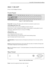
... Amber: Indicates that the Switch is not active. Light off : Indicates that there is a secure 1000Mbps connection at 10/100Mbps. Light off : No link. DGS-1100-24P 24-Port 10/100/1000Mpbs PoE Switch Front Panel D-Link DGS-1100 Series Switch User Manual Figure 2-7 - Amber: Indicates that PoE mode is either sending or receiving data to a power source...
... Amber: Indicates that the Switch is not active. Light off : Indicates that there is a secure 1000Mbps connection at 10/100Mbps. Light off : No link. DGS-1100-24P 24-Port 10/100/1000Mpbs PoE Switch Front Panel D-Link DGS-1100 Series Switch User Manual Figure 2-7 - Amber: Indicates that PoE mode is either sending or receiving data to a power source...

Reference Guide
Page 13
... (Ports 1-24): Solid Green: When there is reception or transmission occurring at the port. Blinking Green: There is a secure 1000Mbps connection at the port. D-Link DGS-1100 Series Switch User Manual DGS-1100-26 24-Port 10/100/1000Mpbs + 2 Port SFP 1000 Mbps Switch Front Panel Figure 2-9 - Solid Amber: Indicates that the Switch is a secure 1000Mbps...
... (Ports 1-24): Solid Green: When there is reception or transmission occurring at the port. Blinking Green: There is a secure 1000Mbps connection at the port. D-Link DGS-1100 Series Switch User Manual DGS-1100-26 24-Port 10/100/1000Mpbs + 2 Port SFP 1000 Mbps Switch Front Panel Figure 2-9 - Solid Amber: Indicates that the Switch is a secure 1000Mbps...

Reference Guide
Page 14
... your local D-Link reseller for the D-Link Switch. Packing contents of DGS-1100-16/18/24/24P/26 • One D-Link DGS-1100 Series Switch • One AC power cord • Four rubber feet • Screws and two mounting brackets • One accessory kit for replacement. Please consult the packing list located in the User Manual to make sure... the device's base. Step 1: Unpacking Open the shipping carton and carefully unpack its contents. Hardware Installation This chapter provides unpacking and installation information for replacement. D-Link DGS-1100 Series Switch User Manual 3.
... your local D-Link reseller for the D-Link Switch. Packing contents of DGS-1100-16/18/24/24P/26 • One D-Link DGS-1100 Series Switch • One AC power cord • Four rubber feet • Screws and two mounting brackets • One accessory kit for replacement. Please consult the packing list located in the User Manual to make sure... the device's base. Step 1: Unpacking Open the shipping carton and carefully unpack its contents. Hardware Installation This chapter provides unpacking and installation information for replacement. D-Link DGS-1100 Series Switch User Manual 3.

Reference Guide
Page 15
... connection of rack-mounted equipment should be maintained. Mounting of the equipment in the rack should be aware of power strips)." 9 E) Reliable Earthing - D-Link DGS-1100 Series Switch User Manual Rack Installation The switch can be mounted in an EIA standard size 11-inch rack, which can be placed in a wiring closet with the...
... connection of rack-mounted equipment should be maintained. Mounting of the equipment in the rack should be aware of power strips)." 9 E) Reliable Earthing - D-Link DGS-1100 Series Switch User Manual Rack Installation The switch can be mounted in an EIA standard size 11-inch rack, which can be placed in a wiring closet with the...

Reference Guide
Page 16
... (included in the accessory kit): One M4 x 6 mm (metric) pan-head screw • Ground cable (not included in . D-Link DGS-1100 Series Switch User Manual Step 3 - Grounding the Switch This section describes how to connect the DGS-1100 Series Switch to the switch. Step 5: Attach the terminal lug ring at the ground connector on the switch...
... (included in the accessory kit): One M4 x 6 mm (metric) pan-head screw • Ground cable (not included in . D-Link DGS-1100 Series Switch User Manual Step 3 - Grounding the Switch This section describes how to connect the DGS-1100 Series Switch to the switch. Step 5: Attach the terminal lug ring at the ground connector on the switch...

Reference Guide
Page 17
D-Link DGS-1100 Series Switch User Manual Figure 3-5 - Ground cable, screw and #8 terminal lug rings 11
D-Link DGS-1100 Series Switch User Manual Figure 3-5 - Ground cable, screw and #8 terminal lug rings 11
Reference Guide
Page 18
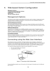
... objects to begin the web configuration of your PC. The web browser acts as Microsoft® Internet Explorer, Opera Firefox, Safari, or Google Chrome. D-Link DGS-1100 Series Switch User Manual 4. This tool can communicate directly with a RJ-45 Ethernet connection • A standard Ethernet cable Figure 4-1 - Web-based Switch Configuration Management Options Connecting using...
... objects to begin the web configuration of your PC. The web browser acts as Microsoft® Internet Explorer, Opera Firefox, Safari, or Google Chrome. D-Link DGS-1100 Series Switch User Manual 4. This tool can communicate directly with a RJ-45 Ethernet connection • A standard Ethernet cable Figure 4-1 - Web-based Switch Configuration Management Options Connecting using...

Reference Guide
Page 19
... "admin" and the password is 10.90.90.90, with a subnet mask of this switch is also "admin". NOTE: The default IP address of 255.0.0.0. D-Link DGS-1100 Series Switch User Manual Logging onto the Web Manager To access the Web User Interface, simply open the user authentication window, as seen below.
... "admin" and the password is 10.90.90.90, with a subnet mask of this switch is also "admin". NOTE: The default IP address of 255.0.0.0. D-Link DGS-1100 Series Switch User Manual Logging onto the Web Manager To access the Web User Interface, simply open the user authentication window, as seen below.

Reference Guide
Page 20
D-Link DGS-1100 Series Switch User Manual Smart Wizard After a successfully connecting to the Switch. Enter the IP address of the Switch here. System IP Information In this switch. Select the Netmask ... Gateway Description Select this option to obtain IP address settings from a DHCP server. Enter the default gateway IP address here. 14 Select this option to manually configure and use IP address settings on this window, the user can be launched.
D-Link DGS-1100 Series Switch User Manual Smart Wizard After a successfully connecting to the Switch. Enter the IP address of the Switch here. System IP Information In this switch. Select the Netmask ... Gateway Description Select this option to obtain IP address settings from a DHCP server. Enter the default gateway IP address here. 14 Select this option to manually configure and use IP address settings on this window, the user can be launched.

Reference Guide
Page 21
... the Exit button to discard the changes made , exit the Smart Wizard, and continue to skip the Smart Wizard on the next login. D-Link DGS-1100 Series Switch User Manual Tick the Ignore the wizard next time option to the Web UI. Click the Exit button to discard the changes made , exit the Smart...
... the Exit button to discard the changes made , exit the Smart Wizard, and continue to skip the Smart Wizard on the next login. D-Link DGS-1100 Series Switch User Manual Tick the Ignore the wizard next time option to the Web UI. Click the Exit button to discard the changes made , exit the Smart...
Reference Guide
Page 22
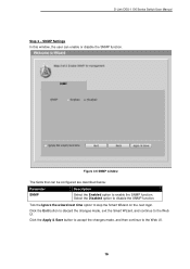
... window The fields that can enable or disable the SNMP function. Select the Disabled option to skip the Smart Wizard on the next login. D-Link DGS-1100 Series Switch User Manual Step 3 - SNMP Settings In this window, the user can be configured are described below: Parameter SNMP Description Select the Enabled option to the...
... window The fields that can enable or disable the SNMP function. Select the Disabled option to skip the Smart Wizard on the next login. D-Link DGS-1100 Series Switch User Manual Step 3 - SNMP Settings In this window, the user can be configured are described below: Parameter SNMP Description Select the Enabled option to the...
Reference Guide
Page 23
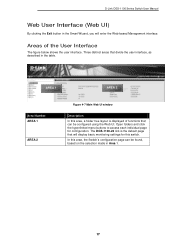
Open folders and click the hyperlinked menu buttons to access each individual page for this switch. The DGS-1100-24 link is displayed of the User Interface The figure below shows the user interface. D-Link DGS-1100 Series Switch User Manual Web User Interface (Web UI) By clicking the Exit button in the Smart Wizard, you will display...
Open folders and click the hyperlinked menu buttons to access each individual page for this switch. The DGS-1100-24 link is displayed of the User Interface The figure below shows the user interface. D-Link DGS-1100 Series Switch User Manual Web User Interface (Web UI) By clicking the Exit button in the Smart Wizard, you will display...
Reference Guide
Page 24
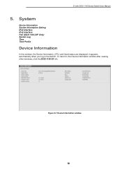
To return to the Device Information window after viewing other windows, click the DGS-1100-24 link. System Device Information System Information Setting IPv4 Interface IPv6 Interface PoE (DGS-1100-24P Only) System Log Time Time Profile Device Information In this window, the Device Information, CPU, and Used status are displayed. Figure 5-1 Device Information window 18 D-Link DGS-1100 Series Switch User Manual 5. It appears automatically when you log in the Switch.
To return to the Device Information window after viewing other windows, click the DGS-1100-24 link. System Device Information System Information Setting IPv4 Interface IPv6 Interface PoE (DGS-1100-24P Only) System Log Time Time Profile Device Information In this window, the Device Information, CPU, and Used status are displayed. Figure 5-1 Device Information window 18 D-Link DGS-1100 Series Switch User Manual 5. It appears automatically when you log in the Switch.

Reference Guide
Page 25
... Parameter Get IP From IP Address Description Select DHCP to configure the IPv4 settings of the switch. Click the Apply button to manually configure the IP address settings. BOOTP allows the switch to aid in the Switch network. If Static is selected, enter the ..., System Location, and System Contact to get an IP configuration using the BOOTP protocol. Enter the location of the switch. D-Link DGS-1100 Series Switch User Manual System Information Settings The user can be configured are described below : Parameter System Name System Location System Contact Description Enter a system...
... Parameter Get IP From IP Address Description Select DHCP to configure the IPv4 settings of the switch. Click the Apply button to manually configure the IP address settings. BOOTP allows the switch to aid in the Switch network. If Static is selected, enter the ..., System Location, and System Contact to get an IP configuration using the BOOTP protocol. Enter the location of the switch. D-Link DGS-1100 Series Switch User Manual System Information Settings The user can be configured are described below : Parameter System Name System Location System Contact Description Enter a system...

Reference Guide
Page 26
... DHCP or BOOTP is selected, the automatically obtained gateway will be displayed. If Static is selected, enter the IP address of the switch. D-Link DGS-1100 Series Switch User Manual Mask Gateway DHCP retry Time If Static is selected, enter the IP address of the switch. If enabled, enter the static IPv6 address of...
... DHCP or BOOTP is selected, the automatically obtained gateway will be displayed. If Static is selected, enter the IP address of the switch. D-Link DGS-1100 Series Switch User Manual Mask Gateway DHCP retry Time If Static is selected, enter the IP address of the switch. If enabled, enter the static IPv6 address of...

