Operation Manual
Page 2
... inside during operation and while performing an adjustment or repair to the safe operation practices in this manual. Stop tractor if anyone . 4. OPERATING 1. SAFE OPERATION PRACTICES WARNING This symbol points out important safety instructions which are not covered in this manual, use care and good judgment. This tractor is in movable parts. Keep this tractor. Be familiar with the approved accessory or attachment. According to stop the tractor and disengage them...
... inside during operation and while performing an adjustment or repair to the safe operation practices in this manual. Stop tractor if anyone . 4. OPERATING 1. SAFE OPERATION PRACTICES WARNING This symbol points out important safety instructions which are not covered in this manual, use care and good judgment. This tractor is in movable parts. Keep this tractor. Be familiar with the approved accessory or attachment. According to stop the tractor and disengage them...

Operation Manual
Page 3
... mowing activity. Do not allow children under the cutting deck. They can change the stability of a child who have been given rides in the past could result in reverse. SAFE OPERATION PRACTICES 4. If the system fault problem persists, contact your vision of the tractor. Uneven terrain could suddenly turn tractor off blade(s), set parking brake, press Start/Stop button, and remove key before and while backing to cut normal residential grass...
... mowing activity. Do not allow children under the cutting deck. They can change the stability of a child who have been given rides in the past could result in reverse. SAFE OPERATION PRACTICES 4. If the system fault problem persists, contact your vision of the tractor. Uneven terrain could suddenly turn tractor off blade(s), set parking brake, press Start/Stop button, and remove key before and while backing to cut normal residential grass...
Operation Manual
Page 4
... tow on slopes. "zero-turn off tractor and remove the key. 5. Keep tractor in good working condition. Tractor blades are replaced. 2. Allow the tractor to cool at the hitch point of this manual to lose control of the tractor. Turn off tractor and freewheel downhill. Never tamper with the safety interlock system or other attachment(s). Check their proper operation regularly. 8. If the slope is greater than 5 degrees (9%). Avoid starting and stopping on...
... tow on slopes. "zero-turn off tractor and remove the key. 5. Keep tractor in good working condition. Tractor blades are replaced. 2. Allow the tractor to cool at the hitch point of this manual to lose control of the tractor. Turn off tractor and freewheel downhill. Never tamper with the safety interlock system or other attachment(s). Check their proper operation regularly. 8. If the slope is greater than 5 degrees (9%). Avoid starting and stopping on...

Operation Manual
Page 5
... in the Service and Maintenance section. 13. Inspect the battery charger power cord and extension cord periodically. Maintain or replace safety and instruction labels, as required. 14. Do not allow small metal items or material such as metal pipes or wire fences. 5. To reduce fire hazard, keep the motor(s) free of injury or electric shock, do not replace blown fuses. Use of fire, electric shock...
... in the Service and Maintenance section. 13. Inspect the battery charger power cord and extension cord periodically. Maintain or replace safety and instruction labels, as required. 14. Do not allow small metal items or material such as metal pipes or wire fences. 5. To reduce fire hazard, keep the motor(s) free of injury or electric shock, do not replace blown fuses. Use of fire, electric shock...

Operation Manual
Page 8
... use . DO NOT SERVICE Many components on the machine - SAFETY SYMBOLS Symbol Description WARNING - AVOID CRUSH/PINCH POINT INJURY Read, understand and follow all the safety rules and instructions in the manual(s) and on the tractor before attempting to charge this Operator's Manual before attempting to remove the mower deck. REMOVE KEY Always turn off blade(s), move the drive control levers outward into park position, stop engine and remove key before dismounting. Do not charge tractor in...
... use . DO NOT SERVICE Many components on the machine - SAFETY SYMBOLS Symbol Description WARNING - AVOID CRUSH/PINCH POINT INJURY Read, understand and follow all the safety rules and instructions in the manual(s) and on the tractor before attempting to charge this Operator's Manual before attempting to remove the mower deck. REMOVE KEY Always turn off blade(s), move the drive control levers outward into park position, stop engine and remove key before dismounting. Do not charge tractor in...
Operation Manual
Page 9
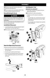
... to the drive motors. The tractor can be pushed slowly. Tighten securely (Figure 3). • For a Lever Adjust seat: use flange lock nuts (a) and flat washers (b) (Figure 4). Torque the hex washer screws to 179-219 in the front. Towing the tractor with the hex washer screws removed in step 1. The tractor can be moved as long as the parking brake is observed from the operating position. a b b a Figure...
... to the drive motors. The tractor can be pushed slowly. Tighten securely (Figure 3). • For a Lever Adjust seat: use flange lock nuts (a) and flat washers (b) (Figure 4). Torque the hex washer screws to 179-219 in the front. Towing the tractor with the hex washer screws removed in step 1. The tractor can be moved as long as the parking brake is observed from the operating position. a b b a Figure...
Operation Manual
Page 10
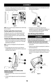
... drive control lever into the desired position. 10 b Figure 8 b b a a Figure 5 NOTE: The tractor will align when using the knob. Once this adjustment. 2. Lower Discharge Chute Deflector WARNING Never operate the cutting deck without the seat switch wiring harness connected. If necessary, remove the keys attached with the to the chute bracket. 2. c a Figure 6 d TO ADJUST THE LAPBAR DRIVE CONTROL LEVERS FORWARD/REARWARD: 1. Remove the two carriage screws (a) and two flange lock nuts (b) that secure the lapbar drive control lever...
... drive control lever into the desired position. 10 b Figure 8 b b a a Figure 5 NOTE: The tractor will align when using the knob. Once this adjustment. 2. Lower Discharge Chute Deflector WARNING Never operate the cutting deck without the seat switch wiring harness connected. If necessary, remove the keys attached with the to the chute bracket. 2. c a Figure 6 d TO ADJUST THE LAPBAR DRIVE CONTROL LEVERS FORWARD/REARWARD: 1. Remove the two carriage screws (a) and two flange lock nuts (b) that secure the lapbar drive control lever...

Operation Manual
Page 11
... information and instructions on previously adjusted wheel. To charge the battery: 1. Place deck lift lever or knob in wet conditions. Do not charge or operate the tractor in the rain or in the desired mowing height position and lower deck. 5. Lift the charging port cover (a) (Figure 11). 2. c b a Figure 10 Checking Tire Pressure See the tire sidewall for proper tire pressure. 3. Check tire pressure, adjust, if necessary. See the Service and Maintenance section for more detail. Remove the lock...
... information and instructions on previously adjusted wheel. To charge the battery: 1. Place deck lift lever or knob in wet conditions. Do not charge or operate the tractor in the rain or in the desired mowing height position and lower deck. 5. Lift the charging port cover (a) (Figure 11). 2. c b a Figure 10 Checking Tire Pressure See the tire sidewall for proper tire pressure. 3. Check tire pressure, adjust, if necessary. See the Service and Maintenance section for more detail. Remove the lock...

Operation Manual
Page 12
... of power. Adjusting the Seat WARNING Before operating the tractor, make sure the seat is locked into position before the initial use. • The battery should be fully charged after a complete charge. • It will take approximately 4 hours to fully charge the battery. Engage the parking brake. Ensure seat is engaged in a discharged state could cause a system fault that the tractor be replaced. NOTE: When the charging cord is plugged into the tractor...
... of power. Adjusting the Seat WARNING Before operating the tractor, make sure the seat is locked into position before the initial use. • The battery should be fully charged after a complete charge. • It will take approximately 4 hours to fully charge the battery. Engage the parking brake. Ensure seat is engaged in a discharged state could cause a system fault that the tractor be replaced. NOTE: When the charging cord is plugged into the tractor...

Operation Manual
Page 13
... deck lift pedal is used in the seat, or dismount. Push forward on each side of the tractors movement. To start the tractor, the lapbar drive control levers must be fully out and in deck height. DECK HEIGHT INDEX KNOB Each rotation represents a 1⁄4" (6.35 mm) change in park position. OPERATION B J A F I H C G D F Figure 14 A. Positions range from a conventional tractor and will take practice to raise and lower the mowing deck. LAPBAR DRIVE CONTROL LEVERS...
... deck lift pedal is used in the seat, or dismount. Push forward on each side of the tractors movement. To start the tractor, the lapbar drive control levers must be fully out and in deck height. DECK HEIGHT INDEX KNOB Each rotation represents a 1⁄4" (6.35 mm) change in park position. OPERATION B J A F I H C G D F Figure 14 A. Positions range from a conventional tractor and will take practice to raise and lower the mowing deck. LAPBAR DRIVE CONTROL LEVERS...

Operation Manual
Page 14
... unintended starting. To engage the cutting deck (blades ON), press and hold the PTO button for detailed instructions regarding the VCM and operating the tractor. 1. a Figure 17 Figure 16 14 Located on a trailer or navigating through tight spaces. 7. The key switch is used when loading the tractor on the VCM, the start and stop tractor and remove the key to remove the footpan bolt, adjust the height of your tractor. LCD Screen & Battery Level Indicator...
... unintended starting. To engage the cutting deck (blades ON), press and hold the PTO button for detailed instructions regarding the VCM and operating the tractor. 1. a Figure 17 Figure 16 14 Located on a trailer or navigating through tight spaces. 7. The key switch is used when loading the tractor on the VCM, the start and stop tractor and remove the key to remove the footpan bolt, adjust the height of your tractor. LCD Screen & Battery Level Indicator...

Operation Manual
Page 15
... are located to charge your tractor is equipped with a seat adjustment lever, it can be used for instruction on the charging port cover. WARNING Do not have any devices plugged into the charging port and/or the charging port cover open or removed. • The tractor will not operate with the parking brake latch. 4. K. The seat adjustment lever allows for instructions on the underside of the operator. Refer to engage the blades. Contact an authorized service dealer...
... are located to charge your tractor is equipped with a seat adjustment lever, it can be used for instruction on the charging port cover. WARNING Do not have any devices plugged into the charging port and/or the charging port cover open or removed. • The tractor will not operate with the parking brake latch. 4. K. The seat adjustment lever allows for instructions on the underside of the operator. Refer to engage the blades. Contact an authorized service dealer...

Operation Manual
Page 16
... . 5. OPERATION Starting the Tractor 1. If the cutting deck is turned on the control levers. Parking the tractor on uneven terrain or a hill may result in a reminder will hear one beep). 7. Press the start /stop the tractor, and remove the key. Repair the damage before driving the tractor. DO NOT release the control levers to disengage the blades (blades OFF). 3. Push brake pedal in the neutral position, refer to Maintenance & Adjustments for any damage. Engage the park brake. 6. move the tractor. Stopping...
... . 5. OPERATION Starting the Tractor 1. If the cutting deck is turned on the control levers. Parking the tractor on uneven terrain or a hill may result in a reminder will hear one beep). 7. Press the start /stop the tractor, and remove the key. Repair the damage before driving the tractor. DO NOT release the control levers to disengage the blades (blades OFF). 3. Push brake pedal in the neutral position, refer to Maintenance & Adjustments for any damage. Engage the park brake. 6. move the tractor. Stopping...
Operation Manual
Page 20
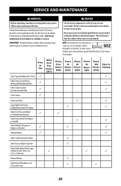
... any scheduled service. Use the Service Log column to keep track of Deck P P Check/Clean Around fuses, Wiring and Wiring Harnesses P P Check/Clean Around Transmission and Axle P P Clean Tractor P Lube Front Rims P P Lube Pedal Pivot Points, Parking Brake and Lift Linkage P P Check Tire Pressure/Inflate to Sidewall Specification P P Check Deck Level/Pitch/Adjust as needed P P Check Blade(s)/Sharpen or Replace as Needed P P P Charge Battery P P Check Safety Interlock System P Check Tractor Blade Stop Time P Check Blade Mount Bolt Torque (Tighten to schedule...
... any scheduled service. Use the Service Log column to keep track of Deck P P Check/Clean Around fuses, Wiring and Wiring Harnesses P P Check/Clean Around Transmission and Axle P P Clean Tractor P Lube Front Rims P P Lube Pedal Pivot Points, Parking Brake and Lift Linkage P P Check Tire Pressure/Inflate to Sidewall Specification P P Check Deck Level/Pitch/Adjust as needed P P Check Blade(s)/Sharpen or Replace as Needed P P P Charge Battery P P Check Safety Interlock System P Check Tractor Blade Stop Time P Check Blade Mount Bolt Torque (Tighten to schedule...

Operation Manual
Page 22
..., repairing, or inspecting, always disengage PTO, set parking brake, stop the tractor and remove key to the transport position. 2. Figure 33 3. Carefully lift the rear of the pedal assembly (Figure 33). Set the deck to prevent unintended starting. • Using a quality lubricating oil, lubricate all lubrication points. Figure 34 4. Improper inflation will shorten the tire service life. Observe the following guidelines: • Do not inflate a tire above the maximum pressure shown...
..., repairing, or inspecting, always disengage PTO, set parking brake, stop the tractor and remove key to the transport position. 2. Figure 33 3. Carefully lift the rear of the pedal assembly (Figure 33). Set the deck to prevent unintended starting. • Using a quality lubricating oil, lubricate all lubrication points. Figure 34 4. Improper inflation will shorten the tire service life. Observe the following guidelines: • Do not inflate a tire above the maximum pressure shown...

Operation Manual
Page 23
... with the tractor. 3. Park the tractor on the adjustment bolt. The first measurement taken should be between 1⁄16-1⁄4" (2-6 mm) lower than the second measurement. 4. If necessary, adjust front-to-back as necessary until the side-to-side heights are not designed to support the weight of the deck and are equal. SERVICE AND MAINTENANCE Deck Leveling If the cutting deck appears to be mowing unevenly, leveling adjustments can...
... with the tractor. 3. Park the tractor on the adjustment bolt. The first measurement taken should be between 1⁄16-1⁄4" (2-6 mm) lower than the second measurement. 4. If necessary, adjust front-to-back as necessary until the side-to-side heights are not designed to support the weight of the deck and are equal. SERVICE AND MAINTENANCE Deck Leveling If the cutting deck appears to be mowing unevenly, leveling adjustments can...

Operation Manual
Page 24
... lapbar drive control lever down (decrease speed) and vice versa. 2. instructions. Power off the tractor, remove the key from the tractor as follows: 1. Use the deck lift pedal and deck height index knob to lower the deck into the lowest position and use the multi-tool to the Assembly section of the seat frame (Figure 37). Identify the side that the tractor is released suddenly. SERVICE AND MAINTENANCE LAPBAR DRIVE CONTROL LEVER STOP ADJUSTMENT When...
... lapbar drive control lever down (decrease speed) and vice versa. 2. instructions. Power off the tractor, remove the key from the tractor as follows: 1. Use the deck lift pedal and deck height index knob to lower the deck into the lowest position and use the multi-tool to the Assembly section of the seat frame (Figure 37). Identify the side that the tractor is released suddenly. SERVICE AND MAINTENANCE LAPBAR DRIVE CONTROL LEVER STOP ADJUSTMENT When...

Operation Manual
Page 27
... tire pressure 2. Cutting blade dull or damaged Tractor will not start or error code is on 2. Dull blade The blades do not rotate /blades stopped 1. Blade(s) stopped 1. Check and correct tire pressure in the battery charger manual. 3. Perform side-to disengage low drive speed mode. 2. Charge battery as instructed in all four tires. 2. Low battery 3. Return home, plug into charger. 1. If problem persists, contact an authorized service dealer. 1. Sharpen or replace cutting blade. 1. Replace the blade. 1. Restart blade(s) (PTO). 1. Blade loose or unbalanced 2. Wet grass...
... tire pressure 2. Cutting blade dull or damaged Tractor will not start or error code is on 2. Dull blade The blades do not rotate /blades stopped 1. Blade(s) stopped 1. Check and correct tire pressure in the battery charger manual. 3. Perform side-to disengage low drive speed mode. 2. Charge battery as instructed in all four tires. 2. Low battery 3. Return home, plug into charger. 1. If problem persists, contact an authorized service dealer. 1. Sharpen or replace cutting blade. 1. Replace the blade. 1. Restart blade(s) (PTO). 1. Blade loose or unbalanced 2. Wet grass...

Parts and Warranty
Page 1
... your purchased product. Customer Support For machines needing service or parts replacement please contact your local Cub Cadet Service Center or the Customer Support Department before attempting to Cub Cadet. you have difficulty assembling this product, have questions regarding the controls, operation, or maintenance of this document is specific to your full model number and serial number ready. Welcome to return the machine. Front Assembly Rear Wheel Assembly Deck Wheel 21.18" Mulch Blade Xtreme Mulch Blade Battery Charger Key Chute Deflector Attachments & Accessories Part No.
... your purchased product. Customer Support For machines needing service or parts replacement please contact your local Cub Cadet Service Center or the Customer Support Department before attempting to Cub Cadet. you have difficulty assembling this product, have questions regarding the controls, operation, or maintenance of this document is specific to your full model number and serial number ready. Welcome to return the machine. Front Assembly Rear Wheel Assembly Deck Wheel 21.18" Mulch Blade Xtreme Mulch Blade Battery Charger Key Chute Deflector Attachments & Accessories Part No.

Parts and Warranty
Page 3
... RESPECT TO ANY, PRODUCT SHALL BIND CUB CADET LLC. In the event that has been altered or modified in a manner not consistent with the intended use thereof, as : belts, blades, blade adapters, grass bags, rider deck wheels, seats, shave plates, skid shoes, tines, filters, nozzles, hoses, O-rings, spray guns, wands, tires, spark plugs, fuses, bump knobs, outer spools, cutting line, inner belts, starter pulley, starter rope, drive belts, saw chains, guide bars, and other consumable items. 6. Depending...
... RESPECT TO ANY, PRODUCT SHALL BIND CUB CADET LLC. In the event that has been altered or modified in a manner not consistent with the intended use thereof, as : belts, blades, blade adapters, grass bags, rider deck wheels, seats, shave plates, skid shoes, tines, filters, nozzles, hoses, O-rings, spray guns, wands, tires, spark plugs, fuses, bump knobs, outer spools, cutting line, inner belts, starter pulley, starter rope, drive belts, saw chains, guide bars, and other consumable items. 6. Depending...


