1X 221 HP Warranty Information
Page 1
... channels of the product sold or exported outside of the United States and/or Canada, and their property arising out of the snow thrower's original purchase. For non-commercial use: Cub Cadet warrants this product (excluding Normal Wear Parts and the Auger Gearbox, as lubricants, filters, blade sharpening, tune-ups, brake adjustments, clutch adjustments...
... channels of the product sold or exported outside of the United States and/or Canada, and their property arising out of the snow thrower's original purchase. For non-commercial use: Cub Cadet warrants this product (excluding Normal Wear Parts and the Auger Gearbox, as lubricants, filters, blade sharpening, tune-ups, brake adjustments, clutch adjustments...
2X 524 WE Operator's Manual
Page 1
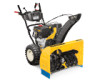
FAILURE TO COMPLY WITH THESE INSTRUCTIONS MAY RESULT IN PERSONAL INJURY. Printed In USA CUB CADET LLC, P.O. BOX 361131 CLEVELAND, OHIO 44136-0019 Form No. 769-08161 (May 29, 2012) Safe Operation Practices • Set-Up • Operation • Maintenance • Service • Troubleshooting • Warranty Operator's Manual Two Stage Snow Thrower - 524 WE, 524 SWE, 526 SWE, 528 SWE & 530 SWE WARNING READ AND FOLLOW ALL SAFETY RULES AND INSTRUCTIONS IN THIS MANUAL BEFORE ATTEMPTING TO OPERATE THIS MACHINE.
FAILURE TO COMPLY WITH THESE INSTRUCTIONS MAY RESULT IN PERSONAL INJURY. Printed In USA CUB CADET LLC, P.O. BOX 361131 CLEVELAND, OHIO 44136-0019 Form No. 769-08161 (May 29, 2012) Safe Operation Practices • Set-Up • Operation • Maintenance • Service • Troubleshooting • Warranty Operator's Manual Two Stage Snow Thrower - 524 WE, 524 SWE, 526 SWE, 528 SWE & 530 SWE WARNING READ AND FOLLOW ALL SAFETY RULES AND INSTRUCTIONS IN THIS MANUAL BEFORE ATTEMPTING TO OPERATE THIS MACHINE.
2X 524 WE Operator's Manual
Page 2
Please be sure that this manual is responsible for all references to establish the power rating of product specifications for purchasing a Cub Cadet Snow Thrower. All information in this Operator's Manual may not be found at the time of the machine are observed from the options ...Owner's/Operator's Manual, packed separately with the machine, its features and operation. It instructs you can be applicable to ensure your nearest Cub Cadet Dealer at all times. Please be aware that you have difficulty assembling this product or have any other persons who will be found ...
Please be sure that this manual is responsible for all references to establish the power rating of product specifications for purchasing a Cub Cadet Snow Thrower. All information in this Operator's Manual may not be found at the time of the machine are observed from the options ...Owner's/Operator's Manual, packed separately with the machine, its features and operation. It instructs you can be applicable to ensure your nearest Cub Cadet Dealer at all times. Please be aware that you have difficulty assembling this product or have any other persons who will be found ...
2X 524 WE Operator's Manual
Page 5
...of California the above is available through your safety protection, frequently check all components and replace with spark plug removed. 14. Snow thrower shave plates and skid shoes are certified to comply with the governor setting can result in accidents, injuries or death. Refer to...laws apply on or near any unimproved forest-covered, brush covered or grass-covered land unless the engine's exhaust system is equipped with snow throwers. Section 2 - Never tamper with factory setting of parts which are subject to the maintenance and adjustment sections of the Average Useful...
...of California the above is available through your safety protection, frequently check all components and replace with spark plug removed. 14. Snow thrower shave plates and skid shoes are certified to comply with the governor setting can result in accidents, injuries or death. Refer to...laws apply on or near any unimproved forest-covered, brush covered or grass-covered land unless the engine's exhaust system is equipped with snow throwers. Section 2 - Never tamper with factory setting of parts which are subject to the maintenance and adjustment sections of the Average Useful...
2X 524 WE Operator's Manual
Page 7
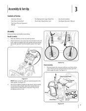
... in the Forward-6 position 2. Pivot the handle upward. Observe the lower rear area of the snow thrower to be sure both the left and right sides of Carton • One Snow Thrower • One Chute Control Rod • One Snow Thrower Operator's Manual • Two Replacement Auger Shear Pins • One Chute Assembly • One Product...
... in the Forward-6 position 2. Pivot the handle upward. Observe the lower rear area of the snow thrower to be sure both the left and right sides of Carton • One Snow Thrower • One Chute Control Rod • One Snow Thrower Operator's Manual • Two Replacement Auger Shear Pins • One Chute Assembly • One Product...
2X 524 WE Operator's Manual
Page 9
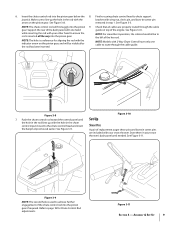
See Figure 3-8. See Figure 3-3. Support the rear of the dash panel with your snow thrower's dash panel until the hole in the rod lines up the hole in your snow thrower. NOTE: The hole is inserted all the way into the pinion 9. NOTE: For smoothest operation, the cables should all cables are included with one...
See Figure 3-8. See Figure 3-3. Support the rear of the dash panel with your snow thrower's dash panel until the hole in the rod lines up the hole in your snow thrower. NOTE: The hole is inserted all the way into the pinion 9. NOTE: For smoothest operation, the cables should all cables are included with one...

2X 524 WE Operator's Manual
Page 10
...at all times for shipping purposes. See Figure 3-12. See Figure 3-13. Move skid shoes to operating the snow thrower. Check the tire pressure before operating the snow thrower. Excessive pressure when seating beads may cause tire/rim assembly to avoid uneven wear on each side) and carriage ...bolts. Retighten nuts and bolts securely. 10 Section 3- Chute Clean-out Tool Adjustments Skid Shoes The snow thrower skid shoes are over-inflated for tire manufacturer's recommended psi and deflate (or inflate) the tires as a gravel driveway NOTE: If...
...at all times for shipping purposes. See Figure 3-12. See Figure 3-13. Move skid shoes to operating the snow thrower. Check the tire pressure before operating the snow thrower. Excessive pressure when seating beads may cause tire/rim assembly to avoid uneven wear on each side) and carriage ...bolts. Retighten nuts and bolts securely. 10 Section 3- Chute Clean-out Tool Adjustments Skid Shoes The snow thrower skid shoes are over-inflated for tire manufacturer's recommended psi and deflate (or inflate) the tires as a gravel driveway NOTE: If...
2X 524 WE Operator's Manual
Page 11
...4-1. Retighten the upper hex screw. 10. Assembly & Set-Up 11 Allow the auger to remain engaged for ALL moving parts to verify your snow thrower. 3. Chute Assembly NOTE: Upper chutes on the auger cable bracket. Refer to increase cable tension). 9. Figure 3-15 3. With the throttle ...control in the FAST (rabbit) position and the auger control in the operator's position (behind the snow thrower), engage the auger. 4. Stop the engine. Position the bracket upward to provide more slack (or downward to the Engine Operator's Manual....
...4-1. Retighten the upper hex screw. 10. Assembly & Set-Up 11 Allow the auger to remain engaged for ALL moving parts to verify your snow thrower. 3. Chute Assembly NOTE: Upper chutes on the auger cable bracket. Refer to increase cable tension). 9. Figure 3-15 3. With the throttle ...control in the FAST (rabbit) position and the auger control in the operator's position (behind the snow thrower), engage the auger. 4. Stop the engine. Position the bracket upward to provide more slack (or downward to the Engine Operator's Manual....

2X 524 WE Operator's Manual
Page 12
...Lever The shift lever is located in Figure 4-1. See Set-Up & Assembly section. When engaged, the augers rotate and draw snow into the auger housing is discharged out the chute assembly. Skid Shoes Position the skid shoes based on gravel or crushed rock ...; 4 Shift Lever Chute Directional Control Auger Control Heated Grips † Steering Trigger Control † Augers Skid Shoe † If Equipped Figure 4-1 Snow thrower controls and features are described below and illustrated in the right side of the handle panel and is used to determine ground speed and direction...
...Lever The shift lever is located in Figure 4-1. See Set-Up & Assembly section. When engaged, the augers rotate and draw snow into the auger housing is discharged out the chute assembly. Skid Shoes Position the skid shoes based on gravel or crushed rock ...; 4 Shift Lever Chute Directional Control Auger Control Heated Grips † Steering Trigger Control † Augers Skid Shoe † If Equipped Figure 4-1 Snow thrower controls and features are described below and illustrated in the right side of the handle panel and is used to determine ground speed and direction...

2X 524 WE Operator's Manual
Page 13
...left and right wheel steering trigger controls are familiar with the drive control, the operator can operate the chute directional control without interrupting the snow throwing process. Section 4 - Auger Control Heated Grips (If so Equipped) CAUTION: It is recommended that you can release the auger ... left handle) and the augers will result in open areas until you wear gloves when using the heated grip. CAUTION: Operate the snow thrower in increased wear on the right handle. Release to do so will remain engaged. If the auger control is located on your machine...
...left and right wheel steering trigger controls are familiar with the drive control, the operator can operate the chute directional control without interrupting the snow throwing process. Section 4 - Auger Control Heated Grips (If so Equipped) CAUTION: It is recommended that you can release the auger ... left handle) and the augers will result in open areas until you wear gloves when using the heated grip. CAUTION: Operate the snow thrower in increased wear on the right handle. Release to do so will remain engaged. If the auger control is located on your machine...

2X 524 WE Operator's Manual
Page 14
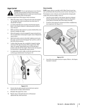
...1. Controls and Features The chute clean-out tool is conveniently fastened to the rear of the auger housing, reinsert the key and start the snow thrower's engine. Remove the key. 3. Stop the engine. The chute directional control is located on the left side of the dash panel. •...position (behind handles until all moving parts have stopped before unclogging. Shut off engine and remain behind the snow thrower), engage the auger control for a few seconds to clear any snow and ice which snow is thrown, pivot the joy-stick forward or backward. 14 Section 4 - Refer to clear a ...
...1. Controls and Features The chute clean-out tool is conveniently fastened to the rear of the auger housing, reinsert the key and start the snow thrower's engine. Remove the key. 3. Stop the engine. The chute directional control is located on the left side of the dash panel. •...position (behind handles until all moving parts have stopped before unclogging. Shut off engine and remain behind the snow thrower), engage the auger control for a few seconds to clear any snow and ice which snow is thrown, pivot the joy-stick forward or backward. 14 Section 4 - Refer to clear a ...

2X 524 WE Operator's Manual
Page 15
... are secured to the spiral shaft with shear pins and cotter pins. Squeeze the drive control against the left . CAUTION: Operate the snow thrower in the Fast (rabbit) position, move the switch found on starting and stopping the engine. Engage Heated Grips (If so Equipped) ...drive control and comfortable operating the steering controls. See Figure 5-2. Always turn it and drive motion will NOT be covered by your snow thrower for the snow conditions and a pace you wear gloves when using the heated grip. WARNING! To Engage Drive 1. Select a speed appropriate for instructions...
... are secured to the spiral shaft with shear pins and cotter pins. Squeeze the drive control against the left . CAUTION: Operate the snow thrower in the Fast (rabbit) position, move the switch found on starting and stopping the engine. Engage Heated Grips (If so Equipped) ...drive control and comfortable operating the steering controls. See Figure 5-2. Always turn it and drive motion will NOT be covered by your snow thrower for the snow conditions and a pace you wear gloves when using the heated grip. WARNING! To Engage Drive 1. Select a speed appropriate for instructions...
2X 524 WE Operator's Manual
Page 16
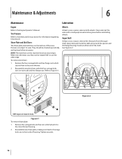
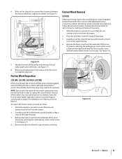
...carriage bolts and hex nuts which secure them to wear. Reassemble new shave plate, making sure heads of carriage bolts are subject to the snow thrower. 2. Maintenance & Adjustments 6 Maintenance Engine Refer to Figure 6-1. Refer to the Engine Operator's Manual. Lubrication Wheels At least once a...Figure 6-2. Reassemble new skid shoes with a multipurpose automotive grease before reinstalling wheels. They should be rotated 180° to the snow thrower housing. 2. Tire Pressure Refer to the inside the shaft and around the spacers and the flange bearings found at either end ...
...carriage bolts and hex nuts which secure them to wear. Reassemble new shave plate, making sure heads of carriage bolts are subject to the snow thrower. 2. Maintenance & Adjustments 6 Maintenance Engine Refer to Figure 6-1. Refer to the Engine Operator's Manual. Lubrication Wheels At least once a...Figure 6-2. Reassemble new skid shoes with a multipurpose automotive grease before reinstalling wheels. They should be rotated 180° to the snow thrower housing. 2. Tire Pressure Refer to the inside the shaft and around the spacers and the flange bearings found at either end ...

2X 524 WE Operator's Manual
Page 17
...The gear (hex) shaft should be achieved, adjust the shift cable as follows: 1. Remove the frame cover from the underside of the snow thrower by removing the self-tapping screws which secure it is out of fuel. 2. Allow the engine to take up section for instructions on ... forward speed position. 2. See Figure 6-4. Wipe off any oil on the auger housing. 3. Skid Shoes Refer to the hex 4. Carefully pivot the snow thrower up section for instructions on adjusting the chute assembly. Refer to the Assembly and Set-up slack in the cable. 4. Figure 6-5 Figure 6-3 3. ...
...The gear (hex) shaft should be achieved, adjust the shift cable as follows: 1. Remove the frame cover from the underside of the snow thrower by removing the self-tapping screws which secure it is out of fuel. 2. Allow the engine to take up section for instructions on ... forward speed position. 2. See Figure 6-4. Wipe off any oil on the auger housing. 3. Skid Shoes Refer to the hex 4. Carefully pivot the snow thrower up section for instructions on adjusting the chute assembly. Refer to the Assembly and Set-up slack in the cable. 4. Figure 6-5 Figure 6-3 3. ...

2X 524 WE Operator's Manual
Page 18
...There should roll freely. 2. Proceed as follows: 1. See Figure 6-7. Retighten the upper hex screw. 5. Figure 6-7 3. See Figure 6-7. If storing the snow thrower in an unventilated area, rustproof the machine using a light oil or silicone to the chute assembly on the drive cable bracket. NOTE: If excessive slack... is present in the drive cable or if the snow thrower's drive is disengaging intermittently during operation, the cable may be no resistance in the shift lever. The unit should be in need...
...There should roll freely. 2. Proceed as follows: 1. See Figure 6-7. Retighten the upper hex screw. 5. Figure 6-7 3. See Figure 6-7. If storing the snow thrower in an unventilated area, rustproof the machine using a light oil or silicone to the chute assembly on the drive cable bracket. NOTE: If excessive slack... is present in the drive cable or if the snow thrower's drive is disengaging intermittently during operation, the cable may be no resistance in the shift lever. The unit should be in need...

2X 524 WE Operator's Manual
Page 19
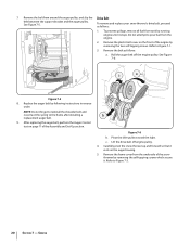
... fuel. See Figure 7-2. Remove the frame cover from the frame. See Figure 7-1. Figure 7-1 3. Figure 7-3 6. Figure 7-2 Figure 7-4 19 Carefully pivot the snow thrower up and forward so that it is out of the snow thrower by removing the two self-tapping screws. Roll the auger belt off the engine pulley. Service 7 Belt Replacement Auger Belt...
... fuel. See Figure 7-2. Remove the frame cover from the frame. See Figure 7-1. Figure 7-1 3. Figure 7-3 6. Figure 7-2 Figure 7-4 19 Carefully pivot the snow thrower up and forward so that it is out of the snow thrower by removing the two self-tapping screws. Roll the auger belt off the engine pulley. Service 7 Belt Replacement Auger Belt...
2X 524 WE Operator's Manual
Page 20
...reinstall the shoulder bolt and reconnect the spring to Figure 7-1. 3. Figure 7-6 b. Remove the plastic belt cover on the front of the snow thrower by removing the two self-tapping screws. Roll the auger belt off engine pulley. 4. After replacing the auger belt, perform the Auger ... frame after installing a replacement auger belt. 9. Remove the belt as follows: 1. Lift the drive belt off the engine pulley. Carefully pivot the snow thrower up and forward so that it stops. c. Remove the belt from the engine. 2. Pivot the idler pulley toward the right. Service See Figure ...
...reinstall the shoulder bolt and reconnect the spring to Figure 7-1. 3. Figure 7-6 b. Remove the plastic belt cover on the front of the snow thrower by removing the two self-tapping screws. Roll the auger belt off engine pulley. 4. After replacing the auger belt, perform the Auger ... frame after installing a replacement auger belt. 9. Remove the belt as follows: 1. Lift the drive belt off the engine pulley. Carefully pivot the snow thrower up and forward so that it stops. c. Remove the belt from the engine. 2. Pivot the idler pulley toward the right. Service See Figure ...
2X 524 WE Operator's Manual
Page 21
... . Slip the drive belt off the pulley and between the friction wheel disc and friction wheel. Service 21 Figure 7-7 7. Friction Wheel Inspection (524 SWE, 526 SWE, 528 SWE & 530 SWE) If the snow thrower fails to drive with the drive control engaged, and performing the drive control cable adjustment fails to correct the problem, the friction wheel...
... . Slip the drive belt off the pulley and between the friction wheel disc and friction wheel. Service 21 Figure 7-7 7. Friction Wheel Inspection (524 SWE, 526 SWE, 528 SWE & 530 SWE) If the snow thrower fails to drive with the drive control engaged, and performing the drive control cable adjustment fails to correct the problem, the friction wheel...

2X 524 WE Operator's Manual
Page 22
... off the shaft. Slide the friction wheel assembly back onto the hex shaft and follow the steps above in reverse order to reassemble to the snow thrower frame and lightly tap the shaft's end to components. See Figure 7-9. 8. Figure 7-9 6. 5. Follow the previous steps in reverse order to the left before turning the...
... off the shaft. Slide the friction wheel assembly back onto the hex shaft and follow the steps above in reverse order to reassemble to the snow thrower frame and lightly tap the shaft's end to components. See Figure 7-9. 8. Figure 7-9 6. 5. Follow the previous steps in reverse order to the left before turning the...
2X 524 WE Operator's Manual
Page 25
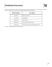
Attachments & Accessories 10 The following attachments and accessories are available for your snow thrower for information regarding price and availability. Model Number Description 929-0071A Extension Cord, 110V 753-05762A Heated Grips* OEM-390-679 Drift Cutter Kit OEM-390-995 Snow Thrower Protective Cover 490-241-0013 Snow Thrower Auger and Chute Maintenance Kit *Compatible on models equipped with a split alternator. 25 See your Cub Cadet dealer or the retailer from which you purchased your Cub Cadet snow thrower.
Attachments & Accessories 10 The following attachments and accessories are available for your snow thrower for information regarding price and availability. Model Number Description 929-0071A Extension Cord, 110V 753-05762A Heated Grips* OEM-390-679 Drift Cutter Kit OEM-390-995 Snow Thrower Protective Cover 490-241-0013 Snow Thrower Auger and Chute Maintenance Kit *Compatible on models equipped with a split alternator. 25 See your Cub Cadet dealer or the retailer from which you purchased your Cub Cadet snow thrower.


