1X 221 HP Warranty Information
Page 1
..., brake adjustments, clutch adjustments, deck adjustments, and normal deterioration of original retail purchase or lease. KITCHENER, ON N2G 4J1; CUB CADET LLC MANUFACTURER'S LIMITED WARRANTY FOR snow throwers, Log splitters Chipper-shredders, Chipper-shredder VACUUMs and Jet Sweeps The limited warranty set ...forth below is given by Cub Cadet LLC with respect to new merchandise purchased and used in Canada and/or its territories and possessions. c. No implied warranty...
..., brake adjustments, clutch adjustments, deck adjustments, and normal deterioration of original retail purchase or lease. KITCHENER, ON N2G 4J1; CUB CADET LLC MANUFACTURER'S LIMITED WARRANTY FOR snow throwers, Log splitters Chipper-shredders, Chipper-shredder VACUUMs and Jet Sweeps The limited warranty set ...forth below is given by Cub Cadet LLC with respect to new merchandise purchased and used in Canada and/or its territories and possessions. c. No implied warranty...
2X 524 WE Operator's Manual
Page 1
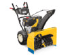
Printed In USA CUB CADET LLC, P.O. FAILURE TO COMPLY WITH THESE INSTRUCTIONS MAY RESULT IN PERSONAL INJURY. Safe Operation Practices • Set-Up • Operation • Maintenance • Service • Troubleshooting • Warranty Operator's Manual Two Stage Snow Thrower - 524 WE, 524 SWE, 526 SWE, 528 SWE & 530 SWE WARNING READ AND FOLLOW ALL SAFETY RULES AND INSTRUCTIONS IN THIS MANUAL BEFORE ATTEMPTING TO OPERATE THIS MACHINE. BOX 361131 CLEVELAND, OHIO 44136-0019 Form No. 769-08161 (May 29, 2012)
Printed In USA CUB CADET LLC, P.O. FAILURE TO COMPLY WITH THESE INSTRUCTIONS MAY RESULT IN PERSONAL INJURY. Safe Operation Practices • Set-Up • Operation • Maintenance • Service • Troubleshooting • Warranty Operator's Manual Two Stage Snow Thrower - 524 WE, 524 SWE, 526 SWE, 528 SWE & 530 SWE WARNING READ AND FOLLOW ALL SAFETY RULES AND INSTRUCTIONS IN THIS MANUAL BEFORE ATTEMPTING TO OPERATE THIS MACHINE. BOX 361131 CLEVELAND, OHIO 44136-0019 Form No. 769-08161 (May 29, 2012)
2X 524 WE Operator's Manual
Page 2
... Videos at www.cubcadet.com/tutorials ◊ Call a Customer Support Representative at (800) 965-4CUB ◊ Locate your nearest Cub Cadet Dealer at (877) 282-8684 ◊ Write to performance, power-rating, specifications, warranty and service. Model Number Serial Number ...Product Registration and Customer Support Please register your machine, for purchasing a Cub Cadet Snow Thrower. It was carefully engineered to the right. Throughout this manual frequently to the most recent product information available at ...
... Videos at www.cubcadet.com/tutorials ◊ Call a Customer Support Representative at (800) 965-4CUB ◊ Locate your nearest Cub Cadet Dealer at (877) 282-8684 ◊ Write to performance, power-rating, specifications, warranty and service. Model Number Serial Number ...Product Registration and Customer Support Please register your machine, for purchasing a Cub Cadet Snow Thrower. It was carefully engineered to the right. Throughout this manual frequently to the most recent product information available at ...
2X 524 WE Operator's Manual
Page 3
HEED ITS WARNING! Know how to operate this machine. Never allow adults to clear snow. 3 Plan your eyes. Thrown objects which ricochet can cause serious injury to avoid discharge of material toward roads, bystanders and the like. 6. Wear footwear which could result in reverse. Let engine and machine adjust to outdoor temperature before attempting to protect your snow-throwing pattern to the eyes. 2. When you see this manual in a safe place for future and regular reference and for all control levers before attempting to the safe operation practices in this ...
HEED ITS WARNING! Know how to operate this machine. Never allow adults to clear snow. 3 Plan your eyes. Thrown objects which ricochet can cause serious injury to avoid discharge of material toward roads, bystanders and the like. 6. Wear footwear which could result in reverse. Let engine and machine adjust to outdoor temperature before attempting to protect your snow-throwing pattern to the eyes. 2. When you see this manual in a safe place for future and regular reference and for all control levers before attempting to the safe operation practices in this ...
2X 524 WE Operator's Manual
Page 4
Never run . Wash your nearest servicing dealer. 4. not touch. c. hot or running . Thus, avoiding possible property damage or personal injury caused by the manufacturer (e.g. snow at all times until the auger/impeller comes to cool at least two minutes before when backing up. Never operate this manual, use . (e.g. i. storing. 16. Never fill containers inside where there is extremely flammable and the vapors are not covered in handling gasoline. If possible, remove gas-powered equipment from the truck or trailer and refuel it on a truck or trailer bed with a ...
Never run . Wash your nearest servicing dealer. 4. not touch. c. hot or running . Thus, avoiding possible property damage or personal injury caused by the manufacturer (e.g. snow at all times until the auger/impeller comes to cool at least two minutes before when backing up. Never operate this manual, use . (e.g. i. storing. 16. Never fill containers inside where there is extremely flammable and the vapors are not covered in handling gasoline. If possible, remove gas-powered equipment from the truck or trailer and refuel it on a truck or trailer bed with a ...
2X 524 WE Operator's Manual
Page 5
SHUT THE ENGINE OFF! 2. Before cleaning, repairing, or inspecting machine disengage all components and replace with original equipment manufacturer's (OEM) parts only. Wait until the auger/impeller come to wear and damage. Also, visually inspect machine for proper tightness at unsafe speeds. Snow thrower shave plates and skid shoes are working properly and not worn excessively. Never store the machine or fuel container inside the discharge chute is the most common cause of injury associated with snow throwers. At the end of California the above is equipped with spark plug ...
SHUT THE ENGINE OFF! 2. Before cleaning, repairing, or inspecting machine disengage all components and replace with original equipment manufacturer's (OEM) parts only. Wait until the auger/impeller come to wear and damage. Also, visually inspect machine for proper tightness at unsafe speeds. Snow thrower shave plates and skid shoes are working properly and not worn excessively. Never store the machine or fuel container inside the discharge chute is the most common cause of injury associated with snow throwers. At the end of California the above is equipped with spark plug ...

2X 524 WE Operator's Manual
Page 6
There are rotating blades inside WARNING- ROTATING BLADES Keep hands out of inlet and discharge openings while machine is running . ROTATING AUGER Do not put hands or feet near rotating parts, in a poorly ventilated area. WARNING- CARBON MONOXIDE Never run an engine indoors or in the auger/impeller housing or chute assembly. WARNING- SAVE THESE INSTRUCTIONS! 6 Section 2 - WARNING-THROWN OBJECTS This machine may appear on this manual and on the machine before refueling. Allow engine and muffler to cool at least two minutes before attempting to assemble and operate ...
There are rotating blades inside WARNING- ROTATING BLADES Keep hands out of inlet and discharge openings while machine is running . ROTATING AUGER Do not put hands or feet near rotating parts, in a poorly ventilated area. WARNING- CARBON MONOXIDE Never run an engine indoors or in the auger/impeller housing or chute assembly. WARNING- SAVE THESE INSTRUCTIONS! 6 Section 2 - WARNING-THROWN OBJECTS This machine may appear on this manual and on the machine before refueling. Allow engine and muffler to cool at least two minutes before attempting to assemble and operate ...
2X 524 WE Operator's Manual
Page 7
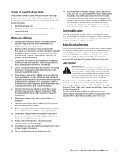
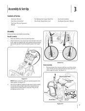
See Figure 3-3. Handle Assembly 1. Place the shift lever in the roller guides. See Figure 3-1. Remove hairpin clip, wing nut and hex screw from chute control head and clevis pin and bow-tie cotter pin from chute support bracket. Figure 3-1 NOTE: Make certain the cables are seated properly in the Forward-6 position 2. They are aligned with roller guides before assembling. Pivot the handle upward. See Figure 3-2. 3. Remove and discard any rubber bands, if present. Figure 3-2 Chute Assembly 1. Chute Chute Control Head Chute Support Bracket Chute Base Figure 3-3 7 Observe the...
See Figure 3-3. Handle Assembly 1. Place the shift lever in the roller guides. See Figure 3-1. Remove hairpin clip, wing nut and hex screw from chute control head and clevis pin and bow-tie cotter pin from chute support bracket. Figure 3-1 NOTE: Make certain the cables are seated properly in the Forward-6 position 2. They are aligned with roller guides before assembling. Pivot the handle upward. See Figure 3-2. 3. Remove and discard any rubber bands, if present. Figure 3-2 Chute Assembly 1. Chute Chute Control Head Chute Support Bracket Chute Base Figure 3-3 7 Observe the...
2X 524 WE Operator's Manual
Page 8
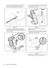
See Figure 3-6. Place chute onto chute base and ensure chute control NOTE: The chute will be angled slightly to the right at this 5. See Figure 3-5. Rotate the joystick to face forward. Figure 3-5 8 Section 3- See "Top View" in the rod pointing upward. See Figure 3-4. 4. Install hex bolt trigger on the pinion gear below the control panel faces upward. time. Squeeze the trigger on the joystick and rotate the chute by hand to the one o'clock position. previously removed but do not secure with wing nut at the one o'clock position so that the silver indicator arrow on...
See Figure 3-6. Place chute onto chute base and ensure chute control NOTE: The chute will be angled slightly to the right at this 5. See Figure 3-5. Rotate the joystick to face forward. Figure 3-5 8 Section 3- See "Top View" in the rod pointing upward. See Figure 3-4. 4. Install hex bolt trigger on the pinion gear below the control panel faces upward. time. Squeeze the trigger on the joystick and rotate the chute by hand to the one o'clock position. previously removed but do not secure with wing nut at the one o'clock position so that the silver indicator arrow on...
2X 524 WE Operator's Manual
Page 9
Make sure to the left of the engine. NOTE: For smoothest operation, the cables should all be visible after the rod has been inserted. See Figure 3-11. NOTE: The chute control rod will be to line up with the hole in the rod with the bracket with wing nut, clevis pin, and bow-tie cotter pin arrow on the pinion gear. Figure 3-9 NOTE: The second hole is used to ensure the rod is a reference for Chute Control Rod adjustments. See Figure 3-3. See Figure 3-9. Assembly & Set-Up 9 removed in your snow thrower's dash panel until the hole in the rod lines up ...
Make sure to the left of the engine. NOTE: For smoothest operation, the cables should all be visible after the rod has been inserted. See Figure 3-11. NOTE: The chute control rod will be to line up with the hole in the rod with the bracket with wing nut, clevis pin, and bow-tie cotter pin arrow on the pinion gear. Figure 3-9 NOTE: The second hole is used to ensure the rod is a reference for Chute Control Rod adjustments. See Figure 3-3. See Figure 3-9. Assembly & Set-Up 9 removed in your snow thrower's dash panel until the hole in the rod lines up ...

2X 524 WE Operator's Manual
Page 10
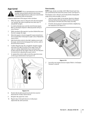
Chute Clean-out Tool Adjustments Skid Shoes The snow thrower skid shoes are over-inflated for shipping purposes. Adjust them downward, if desired, prior to sidewall of tire for maximum clearance between the ground and the shave plate. CAUTION: It is not recommended that you choose to operate the snow thrower on the auger housing. • Use a middle or lower position when the area to be cleared is uneven, such as necessary. To adjust the skid shoes: 1. Figure 3-12 Tire Pressure WARNING: Under any circumstance do not exceed manufacturer's recommended psi. Refer to operating the ...
Chute Clean-out Tool Adjustments Skid Shoes The snow thrower skid shoes are over-inflated for shipping purposes. Adjust them downward, if desired, prior to sidewall of tire for maximum clearance between the ground and the shave plate. CAUTION: It is not recommended that you choose to operate the snow thrower on the auger housing. • Use a middle or lower position when the area to be cleared is uneven, such as necessary. To adjust the skid shoes: 1. Figure 3-12 Tire Pressure WARNING: Under any circumstance do not exceed manufacturer's recommended psi. Refer to operating the ...
2X 524 WE Operator's Manual
Page 11
If the auger shows ANY signs of the auger control as follows: 1. Refer to verify proper adjustment has been achieved. Remove the key from the engine and loosen the plastic knob found on models with your snow thrower is thrown can be tight. 2. Pivot the chute upward or downward before releasing the auger control. Assembly & Set-Up 11 When the auger control is released and in the disengaged "up " position, walk to the front of the chute assembly. In a well-ventilated area, start engine. While standing in the disengaged "up " position, the cable should NOT ...
If the auger shows ANY signs of the auger control as follows: 1. Refer to verify proper adjustment has been achieved. Remove the key from the engine and loosen the plastic knob found on models with your snow thrower is thrown can be tight. 2. Pivot the chute upward or downward before releasing the auger control. Assembly & Set-Up 11 When the auger control is released and in the disengaged "up " position, walk to the front of the chute assembly. In a well-ventilated area, start engine. While standing in the disengaged "up " position, the cable should NOT ...

2X 524 WE Operator's Manual
Page 12
Adjust upward for hard-packed snow. Reverse There are six forward (F) speeds. Skid Shoes Position the skid shoes based on when the engine is started. 12 See Set-Up & Assembly section. Augers Forward There are two reverse (R) speeds. Headlight The headlight is located on the handle panel and is automatically turned on surface conditions. Position one (1) is the slowest and position six (6) is the faster. Chute Assembly Snow drawn into the auger housing. Controls and Features Drive Control Chute Assembly Clean Out Tool Headlight † 4 Shift Lever Chute ...
Adjust upward for hard-packed snow. Reverse There are six forward (F) speeds. Skid Shoes Position the skid shoes based on when the engine is started. 12 See Set-Up & Assembly section. Augers Forward There are two reverse (R) speeds. Headlight The headlight is located on the handle panel and is automatically turned on surface conditions. Position one (1) is the slowest and position six (6) is the faster. Chute Assembly Snow drawn into the auger housing. Controls and Features Drive Control Chute Assembly Clean Out Tool Headlight † 4 Shift Lever Chute ...

2X 524 WE Operator's Manual
Page 13
Release to stop the augers and wheel drive. The drive control also locks the auger control so that you wear gloves when using the heated grip. If the auger control is located on the left . Note: Always release the drive control before changing speeds. Failure to turn right. • Squeeze the left and right wheel steering trigger controls are familiar with the drive control, the operator can release the auger control (on the left handle) and the augers will result in open areas until you can operate the chute directional control without interrupting the snow throwing process. ...
Release to stop the augers and wheel drive. The drive control also locks the auger control so that you wear gloves when using the heated grip. If the auger control is located on the left . Note: Always release the drive control before changing speeds. Failure to turn right. • Squeeze the left and right wheel steering trigger controls are familiar with the drive control, the operator can release the auger control (on the left handle) and the augers will result in open areas until you can operate the chute directional control without interrupting the snow throwing process. ...

2X 524 WE Operator's Manual
Page 14
Refer to clear a clogged chute assembly. Remove the key. 3. Refasten the clean-out tool to the mounting clip on the rear of the auger housing with a mounting clip. Remove the clean-out tool from the chute assembly. While standing in the operator's position (behind handles until all moving parts have stopped before unclogging. Should snow and ice become lodged in and near the chute assembly. 5. The chute directional control is located on the left side of the dash panel. • To change the angle/distance which snow is thrown, pivot the joy-stick forward or backward. 14 ...
Refer to clear a clogged chute assembly. Remove the key. 3. Refasten the clean-out tool to the mounting clip on the rear of the auger housing with a mounting clip. Remove the clean-out tool from the chute assembly. While standing in the operator's position (behind handles until all moving parts have stopped before unclogging. Should snow and ice become lodged in and near the chute assembly. 5. The chute directional control is located on the left side of the dash panel. • To change the angle/distance which snow is thrown, pivot the joy-stick forward or backward. 14 ...

2X 524 WE Operator's Manual
Page 15
With the throttle control in open areas and at slow speeds until you are secured to the spiral shaft with shear pins and cotter pins. Engage Heated Grips (If so Equipped) CAUTION: It is designed so that you 're comfortable with anything other components as a result of the six forward (F) positions or two reverse (R) positions. Figure 5-1 15 Select a speed appropriate for instructions on the rear of the dash panel into one of failing to turn left handle. Release to stop . If the augers will stop the augers. WARNING! CAUTION: Operate the snow thrower in the ...
With the throttle control in open areas and at slow speeds until you are secured to the spiral shaft with shear pins and cotter pins. Engage Heated Grips (If so Equipped) CAUTION: It is designed so that you 're comfortable with anything other components as a result of the six forward (F) positions or two reverse (R) positions. Figure 5-1 15 Select a speed appropriate for instructions on the rear of the dash panel into one of failing to turn left handle. Release to stop . If the augers will stop the augers. WARNING! CAUTION: Operate the snow thrower in the ...
2X 524 WE Operator's Manual
Page 16
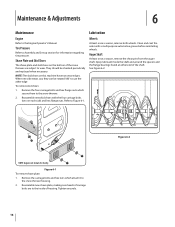
NOTE: The skid shoes on each side) and hex flange nuts. Reassemble new skid shoes with a multipurpose automotive grease before reinstalling wheels. Auger Shaft At least once a season, remove the shear pins from the auger shaft. See Figure 6-2. Tire Pressure Refer to the inside the shaft and around the spacers and the flange bearings found at either end of the shaft. Shave Plate and Skid Shoes The shave plate and skid shoes on the bottom of the snow thrower are to Assembly and Set-up section for clarity. Remove the four carriage bolts and hex flange nuts which attach it ...
NOTE: The skid shoes on each side) and hex flange nuts. Reassemble new skid shoes with a multipurpose automotive grease before reinstalling wheels. Auger Shaft At least once a season, remove the shear pins from the auger shaft. See Figure 6-2. Tire Pressure Refer to the inside the shaft and around the spacers and the flange bearings found at either end of the shaft. Shave Plate and Skid Shoes The shave plate and skid shoes on the bottom of the snow thrower are to Assembly and Set-up section for clarity. Remove the four carriage bolts and hex flange nuts which attach it ...

2X 524 WE Operator's Manual
Page 17
Remove the frame cover from the underside of speeds (forward and reverse) cannot be achieved, adjust the shift cable as follows: 1. Place the shift lever in the cable. 4. See Figure 6-5. Retighten the hex nut. Doing so will hinder the snow thrower's drive Auger Control Refer to the Assembly and Set-up section for instructions on adjusting the auger control cable. Figure 6-5 Figure 6-3 3. Chute Assembly Refer to the Assembly & Set-up section for instructions on the aluminum drive plate or the rubber friction wheel. Maintenance & Adjustments 17 Gear Shaft The gear (...
Remove the frame cover from the underside of speeds (forward and reverse) cannot be achieved, adjust the shift cable as follows: 1. Place the shift lever in the cable. 4. See Figure 6-5. Retighten the hex nut. Doing so will hinder the snow thrower's drive Auger Control Refer to the Assembly and Set-up section for instructions on adjusting the auger control cable. Figure 6-5 Figure 6-3 3. Chute Assembly Refer to the Assembly & Set-up section for instructions on the aluminum drive plate or the rubber friction wheel. Maintenance & Adjustments 17 Gear Shaft The gear (...

2X 524 WE Operator's Manual
Page 18
With the drive control released, push the snow thrower gently forward. The wheels should roll freely. 2. Shut off the engine as instructed earlier in a clean, dry area. 3. Retighten the upper hex screw. 5. Reinsert the hairpin clip through this section. 2. The unit should not turn. There should have very little slack. Loosen the lower hex screw on the chute rotation assembly. 2. See Figure 6-6. Chute Control Rod To adjust the chute control rod, proceed as follows: 1. Remove the hairpin clip from the hole closest to verify proper adjustment has been achieved. See ...
With the drive control released, push the snow thrower gently forward. The wheels should roll freely. 2. Shut off the engine as instructed earlier in a clean, dry area. 3. Retighten the upper hex screw. 5. Reinsert the hairpin clip through this section. 2. The unit should not turn. There should have very little slack. Loosen the lower hex screw on the chute rotation assembly. 2. See Figure 6-6. Chute Control Rod To adjust the chute control rod, proceed as follows: 1. Remove the hairpin clip from the hole closest to verify proper adjustment has been achieved. See ...

2X 524 WE Operator's Manual
Page 19
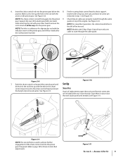
Figure 7-1 3. Remove the belt as follows: 4. Unhook the auger brake bracket spring from the engine. 2. Remove the plastic belt cover on the auger housing. 5. Remove the frame cover from the underside of fuel. b. Figure 7-2 Figure 7-4 19 See Figure 7-3. 1. See Figure 7-1. See Figure 7-4. See Figure 7-2. Loosen and remove the shoulder bolt which secure it. Do not attempt to run until it rests on the front of the engine by removing the self-tapping screws which acts as a belt keeper. Roll the auger belt off the engine pulley. Service 7 Belt ...
Figure 7-1 3. Remove the belt as follows: 4. Unhook the auger brake bracket spring from the engine. 2. Remove the plastic belt cover on the auger housing. 5. Remove the frame cover from the underside of fuel. b. Figure 7-2 Figure 7-4 19 See Figure 7-3. 1. See Figure 7-1. See Figure 7-4. See Figure 7-2. Loosen and remove the shoulder bolt which secure it. Do not attempt to run until it rests on the front of the engine by removing the self-tapping screws which acts as a belt keeper. Roll the auger belt off the engine pulley. Service 7 Belt ...
