Operation Manual
Page 1
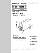
w Safety Rules w Installation w Operation w Maintenance w Parts w Español Sears, Roebuck and Co., Hoffman Estates, IL 60179 U.S.A. Visit the Craftsman web page: www.sears.com/craftsman Operator's Manual OM-194 199E April 2001 210 AMP MIG WELDER Model No. 117.205710 CAUTION: Before using welder, read this manual and follow all its Safety Rules and Operating Instructions.
w Safety Rules w Installation w Operation w Maintenance w Parts w Español Sears, Roebuck and Co., Hoffman Estates, IL 60179 U.S.A. Visit the Craftsman web page: www.sears.com/craftsman Operator's Manual OM-194 199E April 2001 210 AMP MIG WELDER Model No. 117.205710 CAUTION: Before using welder, read this manual and follow all its Safety Rules and Operating Instructions.
Operation Manual
Page 2
... Welding Gun or Cables, Welder, and Welder's Transformer Effective January 1, 2000 Full One Year Warranty for Craftsman Welding Gun or Cables. For three years from the date of purchase, when the welder is in use in material or workmanship, Sears will repair or replace the welding gun or cables free of purchase, when the welding gun or cables are operated and maintained according to the owner's manual instructions...
... Welding Gun or Cables, Welder, and Welder's Transformer Effective January 1, 2000 Full One Year Warranty for Craftsman Welding Gun or Cables. For three years from the date of purchase, when the welder is in use in material or workmanship, Sears will repair or replace the welding gun or cables free of purchase, when the welding gun or cables are operated and maintained according to the owner's manual instructions...
Operation Manual
Page 3
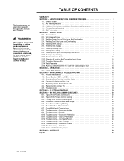
... welding or cutting, produces fumes or gases which contain chemicals known to the State of California to cause birth defects and, in some cases, cancer. (California Health & Safety Code Section 25249.5 et seq.) TABLE OF CONTENTS WARRANTY SECTION 1 - Installing Work Clamp 7 2-6. Changing Input Voltage 9 2-11. Front Panel Controls 14 SECTION 4 - Routine Maintenance 15 4-2. Typical MIG Process Control Settings 21 6-3. Porosity 25 6-10. Troubleshooting - Troubleshooting - Troubleshooting - PARTS LIST 29...
... welding or cutting, produces fumes or gases which contain chemicals known to the State of California to cause birth defects and, in some cases, cancer. (California Health & Safety Code Section 25249.5 et seq.) TABLE OF CONTENTS WARRANTY SECTION 1 - Installing Work Clamp 7 2-6. Changing Input Voltage 9 2-11. Front Panel Controls 14 SECTION 4 - Routine Maintenance 15 4-2. Typical MIG Process Control Settings 21 6-3. Porosity 25 6-10. Troubleshooting - Troubleshooting - Troubleshooting - PARTS LIST 29...
Operation Manual
Page 4
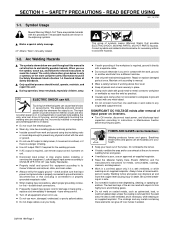
...-metal contact to its Owner's Manual and national, state, and local codes. Touching live electrical parts can be sure that input power cord ground wire is properly connected to a properly grounded receptacle outlet. Incorrectly installed or improperly grounded equipment is well ventilated, and if necessary, while wearing an air-supplied respirator. D Insulate yourself from a different machine. D Use AC output ONLY if...
...-metal contact to its Owner's Manual and national, state, and local codes. Touching live electrical parts can be sure that input power cord ground wire is properly connected to a properly grounded receptacle outlet. Incorrectly installed or improperly grounded equipment is well ventilated, and if necessary, while wearing an air-supplied respirator. D Insulate yourself from a different machine. D Use AC output ONLY if...
Operation Manual
Page 5
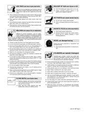
... explosion. D Do not use approved air-supplied respirator. D Always ventilate confined spaces or use welder to prevent welding current from the weld. CYLINDERS can cause fire on a pressurized cylinder - D Use only correct shielding gas cylinders, regulators, hoses, and fittings designed for fire, and keep away. ARC RAYS can cause severe burns. D Welding, chipping, wire brushing, and grinding cause sparks...
... explosion. D Do not use approved air-supplied respirator. D Always ventilate confined spaces or use welder to prevent welding current from the weld. CYLINDERS can cause fire on a pressurized cylinder - D Use only correct shielding gas cylinders, regulators, hoses, and fittings designed for fire, and keep away. ARC RAYS can cause severe burns. D Welding, chipping, wire brushing, and grinding cause sparks...

Operation Manual
Page 6
... installation. D If using line filters, or shielding the work area. D The user is electromagnetically compatible. D Do not press gun trigger until instructed to weld again. Code for Safety in Welding and Cutting, ANSI Standard Z49.1, from pinch points such as robots. Additional Symbols For Installation, Operation, And Maintenance FIRE OR EXPLOSION hazard. D Reduce current or reduce duty cycle before starting to do so. MOVING PARTS...
... installation. D If using line filters, or shielding the work area. D The user is electromagnetically compatible. D Do not press gun trigger until instructed to weld again. Code for Safety in Welding and Cutting, ANSI Standard Z49.1, from pinch points such as robots. Additional Symbols For Installation, Operation, And Maintenance FIRE OR EXPLOSION hazard. D Reduce current or reduce duty cycle before starting to do so. MOVING PARTS...
Operation Manual
Page 8
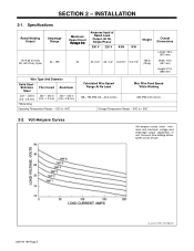
... of unit. SB-180 824 INSTALLATION 2-1. Specifications Rated Welding Output Amperage Range 150 A @ 23 Volts DC, 60% Duty Cycle 30 - 185 Maximum Open-Circuit Voltage DC Amperes Input at Rated Load Output, 60 Hz, Single-Phase 200 V 230 V KVA Weight KW 33 30 (1.6)* 26 (1.4)* 6 (0.27)* 5 (0.13)* 165 lb (75 kg) Overall Dimensions Length: 36 in (915...
... of unit. SB-180 824 INSTALLATION 2-1. Specifications Rated Welding Output Amperage Range 150 A @ 23 Volts DC, 60% Duty Cycle 30 - 185 Maximum Open-Circuit Voltage DC Amperes Input at Rated Load Output, 60 Hz, Single-Phase 200 V 230 V KVA Weight KW 33 30 (1.6)* 26 (1.4)* 6 (0.27)* 5 (0.13)* 165 lb (75 kg) Overall Dimensions Length: 36 in (915...
Operation Manual
Page 10
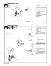
... stationary support so cylinder cannot fall and break off valve. 1 Cap 2 Cylinder Valve Remove cap, stand to terminal and cover connection with O-ring between regulator/flowmeter gas hose connection, and fitting on rear of valve, and open valve slightly. Check wire manufacturer's recommended flow rate. 8 CO2 Adapter (Customer Supplied) 9 O-Ring (Customer Supplied) Install adapter with boot. 4 Hardware 5 Work Clamp Route cable through clamp handle and...
... stationary support so cylinder cannot fall and break off valve. 1 Cap 2 Cylinder Valve Remove cap, stand to terminal and cover connection with O-ring between regulator/flowmeter gas hose connection, and fitting on rear of valve, and open valve slightly. Check wire manufacturer's recommended flow rate. 8 CO2 Adapter (Customer Supplied) 9 O-Ring (Customer Supplied) Install adapter with boot. 4 Hardware 5 Work Clamp Route cable through clamp handle and...
Operation Manual
Page 12
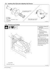
... slide sleeving over and secure in OM-194 199 Page 9 ST-801 580-A Fold sleeving over end of S1. Tools Needed: 15/16 in (200 mm) spools. Installing Wire Spool And Adjusting Hub Tension Use compression spring with 8 in 2-10. Changing Input Voltage 2 3 When a slight force is set for 230 volts. 1 Transformer T1 2 Rear Of Power Switch S1 3 Lead Marked 230 Volt And Fan Motor...
... slide sleeving over and secure in OM-194 199 Page 9 ST-801 580-A Fold sleeving over end of S1. Tools Needed: 15/16 in (200 mm) spools. Installing Wire Spool And Adjusting Hub Tension Use compression spring with 8 in 2-10. Changing Input Voltage 2 3 When a slight force is set for 230 volts. 1 Transformer T1 2 Rear Of Power Switch S1 3 Lead Marked 230 Volt And Fan Motor...
Operation Manual
Page 14
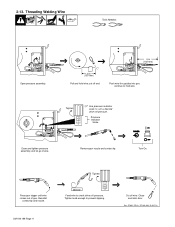
... Scale Close and tighten pressure assembly, and let go of gun. Remove gun nozzle and contact tip. Press gun trigger until wire comes out of wire. Close and latch door. continue to prevent slipping. Turn On. Reinstall contact tip and nozzle. 2-13. Threading Welding Wire Tools Needed: Open pressure assembly. 4 in (102 mm) 6 in (150 mm) Pull and hold wire. cut off wire. Push wire thru guides into gun; Tighten 1 2 3 4 . Tighten knob enough to hold...
... Scale Close and tighten pressure assembly, and let go of gun. Remove gun nozzle and contact tip. Press gun trigger until wire comes out of wire. Close and latch door. continue to prevent slipping. Turn On. Reinstall contact tip and nozzle. 2-13. Threading Welding Wire Tools Needed: Open pressure assembly. 4 in (102 mm) 6 in (150 mm) Pull and hold wire. cut off wire. Push wire thru guides into gun; Tighten 1 2 3 4 . Tighten knob enough to hold...

Operation Manual
Page 15
...- .035 Wire Speed 60 50 40 30 25 20 10 - - - - - - Wire Speed is a starting value only, and can be adjusted while welding. Voltage Tap 6 5 4 3 3 2 2 2 - - - - .035 Wire Speed 70 60 50 45 40 30 20 10 - - - - Voltage Tap 5 4 4 4 3 3 3 2 2 2 .023 Wire Speed 95 85 80... 3 2 2 2 - - - - .035 Wire Speed 65 40 40 30 30 25 20 10 - - - - *Do not change Voltage switch position while welding. Weld Parameter Wire Type, Shielding Gas, And Flow Rate Wire Diameter (inch) Operator Controls Material Thickness 3/8 in (9.5 mm) 1/4 in 3/...
...- .035 Wire Speed 60 50 40 30 25 20 10 - - - - - - Wire Speed is a starting value only, and can be adjusted while welding. Voltage Tap 6 5 4 3 3 2 2 2 - - - - .035 Wire Speed 70 60 50 45 40 30 20 10 - - - - Voltage Tap 5 4 4 4 3 3 3 2 2 2 .023 Wire Speed 95 85 80... 3 2 2 2 - - - - .035 Wire Speed 65 40 40 30 30 25 20 10 - - - - *Do not change Voltage switch position while welding. Weld Parameter Wire Type, Shielding Gas, And Flow Rate Wire Diameter (inch) Operator Controls Material Thickness 3/8 in (9.5 mm) 1/4 in 3/...

Operation Manual
Page 18
... trigger circuit from overload. Press button to drive motor shaft. 4-2. Close door. 4-3. Maintain more often during severe conditions. 3 Months Replace Damaged Or Unreadable Labels 6 Months Repair Or Replace Cracked Cables And Cords Clean And Tighten Weld Terminals Blow Out Or Vacuum Inside Remove drive roll and apply light coat of hole. ST-801 569-A If CB1 opens, weld output stops. Changing Drive Roll And Inlet Wire Guide Tools Needed...
... trigger circuit from overload. Press button to drive motor shaft. 4-2. Close door. 4-3. Maintain more often during severe conditions. 3 Months Replace Damaged Or Unreadable Labels 6 Months Repair Or Replace Cracked Cables And Cords Clean And Tighten Weld Terminals Blow Out Or Vacuum Inside Remove drive roll and apply light coat of hole. ST-801 569-A If CB1 opens, weld output stops. Changing Drive Roll And Inlet Wire Guide Tools Needed...

Operation Manual
Page 19
Cleaning Or Replacing Gun Liner Y Disconnect gun first. 3/8 in Lay gun cable out straight before installing new liner. Remove liner. Ref. 4-4. Blow out gun casing. Install and tighten wire outlet guide. Install adapter, contact tip, and nozzle. ST-800 797-C OM-194 199 Page 16 Tools Needed: 3/8 in Head Tube Remove nozzle, contact tip, and adapter. Cut liner off 3/4 in (20 mm) (3/8 in [9.5 mm] for aluminum) from head tube. To Reassemble Gun: Insert new liner.
Cleaning Or Replacing Gun Liner Y Disconnect gun first. 3/8 in Lay gun cable out straight before installing new liner. Remove liner. Ref. 4-4. Blow out gun casing. Install and tighten wire outlet guide. Install adapter, contact tip, and nozzle. ST-800 797-C OM-194 199 Page 16 Tools Needed: 3/8 in Head Tube Remove nozzle, contact tip, and adapter. Cut liner off 3/4 in (20 mm) (3/8 in [9.5 mm] for aluminum) from head tube. To Reassemble Gun: Insert new liner.

Operation Manual
Page 20
Tools Needed: 3/4 in vice. 3 Slide handle. 2 Remove switch housing. Install switch back into connector cable. 7 Place head tube in vice and tighten until nuts are tight. 8 Remove from vice and turn head tube out by hand. 6 Install existing shock washer onto new head tube. Reposition handle and install switch housing. If replacing head tube, continue to end of new switch (polarity is not important). ST-800 795-C Note: If installing new switch, push switch lead connectors onto terminal...
Tools Needed: 3/4 in vice. 3 Slide handle. 2 Remove switch housing. Install switch back into connector cable. 7 Place head tube in vice and tighten until nuts are tight. 8 Remove from vice and turn head tube out by hand. 6 Install existing shock washer onto new head tube. Reposition handle and install switch housing. If replacing head tube, continue to end of new switch (polarity is not important). ST-800 795-C Note: If installing new switch, push switch lead connectors onto terminal...
Operation Manual
Page 21
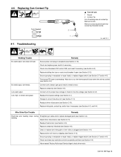
... nearest Factory Authorized Service Agent check drive motor. Replacing Gun Contact Tip Tools Needed: 4-7. Remove nozzle. Low weld output. Low, high, or erratic wire speed. Remedy Secure power cord plug in receptacle or repair leads, or replace trigger switch (see Section 4-4). the thermostat will close when the unit has cooled (see Sections 4-3, and 4-4). Replace inlet guide, contact tip, and/or liner if necessary (see Section 2-3). Replace drive roll if worn...
... nearest Factory Authorized Service Agent check drive motor. Replacing Gun Contact Tip Tools Needed: 4-7. Remove nozzle. Low weld output. Low, high, or erratic wire speed. Remedy Secure power cord plug in receptacle or repair leads, or replace trigger switch (see Section 4-4). the thermostat will close when the unit has cooled (see Sections 4-3, and 4-4). Replace inlet guide, contact tip, and/or liner if necessary (see Section 2-3). Replace drive roll if worn...

Operation Manual
Page 30
... out of the weld bead. Unsteady hand. S-0641 S-0642 OM-194 199 Page 27 6-14. Distortion Base metal moves in (13 mm) beyond nozzle. Make tack welds along joint before starting welding operation. Troubleshooting - Be sure welding wire extends not more than 1/2 in the direction of nozzle. Corrective Actions Use restraint (clamp) to move. Troubleshooting - Waviness Of Bead Waviness Of...
... out of the weld bead. Unsteady hand. S-0641 S-0642 OM-194 199 Page 27 6-14. Distortion Base metal moves in (13 mm) beyond nozzle. Make tack welds along joint before starting welding operation. Troubleshooting - Be sure welding wire extends not more than 1/2 in the direction of nozzle. Corrective Actions Use restraint (clamp) to move. Troubleshooting - Waviness Of Bead Waviness Of...
Operation Manual
Page 33
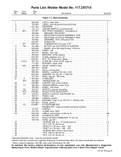
... . . SWITCH, selector 6 position 1 . . . 26 . . . . CLAMP, work 300A 1 . . . 36 600 318 . . Model number required when ordering parts from a Sears Parts/Repair Center. Main Assembly . . . 1 089 899 . . RECTIFIER SI DIODE ASSEMBLY, POS 1 191 376 . . . . MOTOR, fan 230V 60/50 Hz 3000RPM 1 . . . 7 005 656 . . . . BASE 1 . . . 17 203 417 . . HANDLE, switch 1 . . . 30 057 357 . . HANDLE 1 . . . 35 130 750 . . HOSE, gas 5ft 1 . . . 37 SCREW, 008-15 x .37 hexwhd-pln stl 13 . . . 38 NUT, 375...
... . . SWITCH, selector 6 position 1 . . . 26 . . . . CLAMP, work 300A 1 . . . 36 600 318 . . Model number required when ordering parts from a Sears Parts/Repair Center. Main Assembly . . . 1 089 899 . . RECTIFIER SI DIODE ASSEMBLY, POS 1 191 376 . . . . MOTOR, fan 230V 60/50 Hz 3000RPM 1 . . . 7 005 656 . . . . BASE 1 . . . 17 203 417 . . HANDLE, switch 1 . . . 30 057 357 . . HANDLE 1 . . . 35 130 750 . . HOSE, gas 5ft 1 . . . 37 SCREW, 008-15 x .37 hexwhd-pln stl 13 . . . 38 NUT, 375...
Operation Manual
Page 35
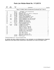
... the factory original performance of your equipment, use only Manufacturer's Suggested Replacement Parts. GROMMET, scr No. 8/10 panel hole 4 . . . 16 180 927 . . CIRCUIT BREAKER, man reset 5A 250V 1 . . . 25 097 421 . . RELAY, encl 24VAC DPDT 20 1 . . . 28 Fig 7-4 . . PLATE, switch 1 *Standard hardware item - Model number required when ordering parts from a Sears Parts/Repair Center. Part No. BRACKET, consumable/tool tray 1 202 449 . . OM-194 199...
... the factory original performance of your equipment, use only Manufacturer's Suggested Replacement Parts. GROMMET, scr No. 8/10 panel hole 4 . . . 16 180 927 . . CIRCUIT BREAKER, man reset 5A 250V 1 . . . 25 097 421 . . RELAY, encl 24VAC DPDT 20 1 . . . 28 Fig 7-4 . . PLATE, switch 1 *Standard hardware item - Model number required when ordering parts from a Sears Parts/Repair Center. Part No. BRACKET, consumable/tool tray 1 202 449 . . OM-194 199...
Operation Manual
Page 36
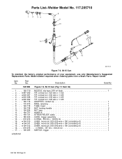
... rbr 1 . . . 17 . . . . . 196 255 . . No. NUT, locking handle 2 . . . 10 . . . . . 194 524 . . CORD, trigger assembly 1 . . . 14 . . . . . 079 974 . . STRAIN RELIEF, cable 2 . . . 13 . . . . . 180 433 . . LINER, monocoil .035/.045 wire x 15ft (consisting of 1 . . . 15 . . . ♦194 012 . . Item Part No. Description Quantity 169 589 Figure 7-3. SWITCH, trigger 1 ♦Optional OM-194 199 Page 33 Model number required when ordering parts from a Sears Parts /Repair Center. TIP, contact scr .035...
... rbr 1 . . . 17 . . . . . 196 255 . . No. NUT, locking handle 2 . . . 10 . . . . . 194 524 . . CORD, trigger assembly 1 . . . 14 . . . . . 079 974 . . STRAIN RELIEF, cable 2 . . . 13 . . . . . 180 433 . . LINER, monocoil .035/.045 wire x 15ft (consisting of 1 . . . 15 . . . ♦194 012 . . Item Part No. Description Quantity 169 589 Figure 7-3. SWITCH, trigger 1 ♦Optional OM-194 199 Page 33 Model number required when ordering parts from a Sears Parts /Repair Center. TIP, contact scr .035...

Operation Manual
Page 37
... . SCREW 3 . . . 15 090 423 . . Drive Assembly, Wire ST-181 053-A *Standard hardware item - MOTOR, gear 24VDC 1 . . . 2 180 929 . . KNOB, adjustment tension 1 . . . 5 090 415 . . . . ROLL, drive V groove .023-.035 1 . . . 16 058 549 . . No. Drive Assembly, Wire (Fig 7-2 Item 29) . . . 1 196 237 . . HOUSING, wire drive 1 . . . 10 090 443 . . . . HOUSING, motor drive 1 . . . 3 198 789 . . DRIVE ASSEMBLY, wire (consisting of your equipment, use only Manufacturer's Suggested Replacement Parts. Hardware is common and not available unless listed. 4 5 6 7 8 9 3 10...
... . SCREW 3 . . . 15 090 423 . . Drive Assembly, Wire ST-181 053-A *Standard hardware item - MOTOR, gear 24VDC 1 . . . 2 180 929 . . KNOB, adjustment tension 1 . . . 5 090 415 . . . . ROLL, drive V groove .023-.035 1 . . . 16 058 549 . . No. Drive Assembly, Wire (Fig 7-2 Item 29) . . . 1 196 237 . . HOUSING, wire drive 1 . . . 10 090 443 . . . . HOUSING, motor drive 1 . . . 3 198 789 . . DRIVE ASSEMBLY, wire (consisting of your equipment, use only Manufacturer's Suggested Replacement Parts. Hardware is common and not available unless listed. 4 5 6 7 8 9 3 10...


