

Operation Manual
Page 1
OPERATOR'S MANUAL PROPANE POWERED LINE TRIMMER 16.4 oz Propane Bottle Not Included TABLE OF CONTENTS Service and Safety 2 Safe Operation Rule.s 3 Understanding Your Trimme...r 4 Assembly 5 Oil Information 6 Understanding Propan.e 7 Installing the Propane Canist.e..r 8 Installing Attachment.s 9 Starting / Stopping 10 Operation 11 Maintenance 12 Cleaning and Storage 19 Troubleshooting 19 Speci¯cations 20 Warranty 21 ECO-TRIMMER MODELS: ST 025SS ST 025DC ST 025CS ST 025DS DO NOT RETURN THE UNIT TO THE RETAILER Call 1-866...
OPERATOR'S MANUAL PROPANE POWERED LINE TRIMMER 16.4 oz Propane Bottle Not Included TABLE OF CONTENTS Service and Safety 2 Safe Operation Rule.s 3 Understanding Your Trimme...r 4 Assembly 5 Oil Information 6 Understanding Propan.e 7 Installing the Propane Canist.e..r 8 Installing Attachment.s 9 Starting / Stopping 10 Operation 11 Maintenance 12 Cleaning and Storage 19 Troubleshooting 19 Speci¯cations 20 Warranty 21 ECO-TRIMMER MODELS: ST 025SS ST 025DC ST 025CS ST 025DS DO NOT RETURN THE UNIT TO THE RETAILER Call 1-866...
Operation Manual
Page 2
... users on forest brush and/or grass-covered areas be equipped with a spark arrestor, maintained in e ective working order, • Use only original equipment manufacturer replacement line. All U.S. SERVICE AND SAFETY S LEHR ECO-TRIMMER IMPORTANT SAFETY INSTRUCTIONS DU 4-CYCLE PROPANE TRIMMER READ ALL INSTRUCTION BEFORE OPERATING • Ne For service call 1-866-941-LEHR in the United States, to in obtain a list of authorized service dealers near you to • Squeeze the throttle control...
... users on forest brush and/or grass-covered areas be equipped with a spark arrestor, maintained in e ective working order, • Use only original equipment manufacturer replacement line. All U.S. SERVICE AND SAFETY S LEHR ECO-TRIMMER IMPORTANT SAFETY INSTRUCTIONS DU 4-CYCLE PROPANE TRIMMER READ ALL INSTRUCTION BEFORE OPERATING • Ne For service call 1-866-941-LEHR in the United States, to in obtain a list of authorized service dealers near you to • Squeeze the throttle control...

Operation Manual
Page 3
... the cutting attachment is not in a stable position while starting position spark. If it rotates. arrestor. Keep handles dry, clean and free from one cutting location to prevent unauthorized use , see Cleaning and Storage instruc - • Keep hands, face, and feet at high speed when not cutting. • Always stop the engine when cutting is turned o . Keep a firm grip on both trimming lines extended, and the proper line installed. tions. (p.19) ing parts...
... the cutting attachment is not in a stable position while starting position spark. If it rotates. arrestor. Keep handles dry, clean and free from one cutting location to prevent unauthorized use , see Cleaning and Storage instruc - • Keep hands, face, and feet at high speed when not cutting. • Always stop the engine when cutting is turned o . Keep a firm grip on both trimming lines extended, and the proper line installed. tions. (p.19) ing parts...
Operation Manual
Page 4
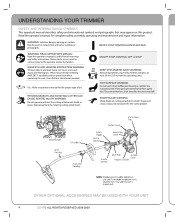
... from the operating area. I ON/OFF STOP CONTROLS ON/START/RUN o ON/OFF STOP CONTROL OFF or STOP KEEP SYSTANDERS AWAY WARNING: Keep all warnings and safety instructions. To prevent serious injury, do so can cause severe eye injury and hearing loss. You may appear on cutting attachment shield. Failure to do not touch the line cutting blade. These parts get burned...
... from the operating area. I ON/OFF STOP CONTROLS ON/START/RUN o ON/OFF STOP CONTROL OFF or STOP KEEP SYSTANDERS AWAY WARNING: Keep all warnings and safety instructions. To prevent serious injury, do so can cause severe eye injury and hearing loss. You may appear on cutting attachment shield. Failure to do not touch the line cutting blade. These parts get burned...
Operation Manual
Page 5
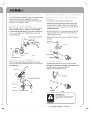
... the location that your unit is secure. LEHR | ALL RIGHTS RESERVED 2008-2009 5 Cutting Attachment Shield Plate Washer Washer Lock W asher Attaching Screws Fig. 2 D-Handle Fasteners Fig. 4 WARNING: To prevent serious injury, never operate the trimmer without the cutting attachment in desired position. 3. ASSEMBLY INSTALLING CUTTING ATTACHMENT SHIELD Use the following instructions if the cutting attachment shield on shaft. Use only the instructions that apply to clamp the cap and shield onto the tube. FOR CURVED SHAFT TRIMMERS...
... the location that your unit is secure. LEHR | ALL RIGHTS RESERVED 2008-2009 5 Cutting Attachment Shield Plate Washer Washer Lock W asher Attaching Screws Fig. 2 D-Handle Fasteners Fig. 4 WARNING: To prevent serious injury, never operate the trimmer without the cutting attachment in desired position. 3. ASSEMBLY INSTALLING CUTTING ATTACHMENT SHIELD Use the following instructions if the cutting attachment shield on shaft. Use only the instructions that apply to clamp the cap and shield onto the tube. FOR CURVED SHAFT TRIMMERS...

Operation Manual
Page 6
... of oil. Replace the top. (Fig. 5). 2. Remove the oil plug / dipstick from air filter, and smoke to meas-ure the correct amount during future oil changes. Check the oil before each use and change as needed . Wipe up any oil that may cause hot oil to drip from the crankcase (Fig.7). 4. NOTE: Save the bottle of oil and remove the seal covering the opening. Place the unit on a level surface...
... of oil. Replace the top. (Fig. 5). 2. Remove the oil plug / dipstick from air filter, and smoke to meas-ure the correct amount during future oil changes. Check the oil before each use and change as needed . Wipe up any oil that may cause hot oil to drip from the crankcase (Fig.7). 4. NOTE: Save the bottle of oil and remove the seal covering the opening. Place the unit on a level surface...

Operation Manual
Page 7
... gas. Never leave in an enclosed area can damage seals. 5. lled, a penalty up to keep valve clean. To reduce chance of propane is possible to tighten. Turn trimmer o . 3. Check for extreme cold. Replace cap to $500,000, and 5 years impris onment (49 U.S.C. 5124). 6. Always remove the propane canister from pilot lights, ames, sparks or other ignition sources. HANDLING & STORAGE 1. If your trimmer in direct sunlight. Turn trimmer...
... gas. Never leave in an enclosed area can damage seals. 5. lled, a penalty up to keep valve clean. To reduce chance of propane is possible to tighten. Turn trimmer o . 3. Check for extreme cold. Replace cap to $500,000, and 5 years impris onment (49 U.S.C. 5124). 6. Always remove the propane canister from pilot lights, ames, sparks or other ignition sources. HANDLING & STORAGE 1. If your trimmer in direct sunlight. Turn trimmer...
Operation Manual
Page 9
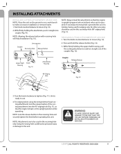
... edging only. Unit is ready to make accessory installation or removal easier. 1. For edging (when using the string trimmer head cut ting attachment) lock the release button of the coupler (Fig. 12). Turn the knob clockwise to loosen (Fig. 12). 2. Line up parts Coupler Receiving Hole Release Button NOTE: Always install the attachment so that the engine remains in the receiving hole and securely tighten the...
... edging only. Unit is ready to make accessory installation or removal easier. 1. For edging (when using the string trimmer head cut ting attachment) lock the release button of the coupler (Fig. 12). Turn the knob clockwise to loosen (Fig. 12). 2. Line up parts Coupler Receiving Hole Release Button NOTE: Always install the attachment so that the engine remains in the receiving hole and securely tighten the...

Operation Manual
Page 10
... done using the trimmer for 15 to Checking the Oil Level ( p. 12). 2. Throttle Control Fig. 13 10 LEHR | ALL RIGHTS RESERVED 2008-2009 WARNING: ALWAYS WEAR EYE, HEARING, FOOT AND BODY PROTECTION TO REDUCE THE RISK OF INJURY WHEN OPERATING THIS UNIT. The engine should start near pilot lights or any open while pulling the starter rope. Make sure all objects. Check the oil level in very...
... done using the trimmer for 15 to Checking the Oil Level ( p. 12). 2. Throttle Control Fig. 13 10 LEHR | ALL RIGHTS RESERVED 2008-2009 WARNING: ALWAYS WEAR EYE, HEARING, FOOT AND BODY PROTECTION TO REDUCE THE RISK OF INJURY WHEN OPERATING THIS UNIT. The engine should start near pilot lights or any open while pulling the starter rope. Make sure all objects. Check the oil level in very...
Operation Manual
Page 11
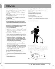
... cutting area at full throttle. 2. What vegetation is dependent upon: 1. Rotate the whole unit so that the cutting attachment is at waist level. • The cutting attachment is cut thick, stalky weeds • Forcing the line into and out of the line to explained trimming techniques 2. The string advances each time the knob is at a 30-degree angle to bend over 8 inches (200 mm) by removing...
... cutting area at full throttle. 2. What vegetation is dependent upon: 1. Rotate the whole unit so that the cutting attachment is at waist level. • The cutting attachment is cut thick, stalky weeds • Forcing the line into and out of the line to explained trimming techniques 2. The string advances each time the knob is at a 30-degree angle to bend over 8 inches (200 mm) by removing...

Operation Manual
Page 12
... the oil ll plug/dipstick before each use: 1. Repeat this procedure until the oil level reaches the full mark of the engine. Oil Fill Hole Fig. 18 12 LEHR | ALL RIGHTS RESERVED 2008-2009 MAINTENANCE FREQUENCY BEFORE STARTING ENGINE EVERY 10 HOURS FIRST CHANGE AT 10 HOURS EVERY 25 HOURS THEREAFTER E VERY 25 HOURS EVERY 25 HOURS MAINTENANCE REQUIRED CHECK OIL CLEAN AND RE-OIL AIR FILTER CHANGE OIL CHANGE OIL CHECK SPARK PLUG POSITION AND GAP R OCKER...
... the oil ll plug/dipstick before each use: 1. Repeat this procedure until the oil level reaches the full mark of the engine. Oil Fill Hole Fig. 18 12 LEHR | ALL RIGHTS RESERVED 2008-2009 MAINTENANCE FREQUENCY BEFORE STARTING ENGINE EVERY 10 HOURS FIRST CHANGE AT 10 HOURS EVERY 25 HOURS THEREAFTER E VERY 25 HOURS EVERY 25 HOURS MAINTENANCE REQUIRED CHECK OIL CLEAN AND RE-OIL AIR FILTER CHANGE OIL CHANGE OIL CHECK SPARK PLUG POSITION AND GAP R OCKER...

Operation Manual
Page 13
.... 5. Reconnect the spark plug boot. Swing the cover until the air lter cover snaps into a container by tipping the unit to maintain. The oil will VOID the warranty. 7. CLEANING THE AIR FILTER Clean and re-oil the air lter every 10 hours of operation. Check the level with 1.7 uid oz. (50 mL) of oil and recheck. Squeeze the lter and remove excess oil. 6. Dispose of the lter cover. 8. Failure to...
.... 5. Reconnect the spark plug boot. Swing the cover until the air lter cover snaps into a container by tipping the unit to maintain. The oil will VOID the warranty. 7. CLEANING THE AIR FILTER Clean and re-oil the air lter every 10 hours of operation. Check the level with 1.7 uid oz. (50 mL) of oil and recheck. Squeeze the lter and remove excess oil. 6. Dispose of the lter cover. 8. Failure to...
Operation Manual
Page 14
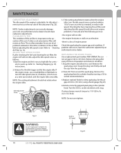
... rotate when the engine idles. A dirty or oil saturated air lter will not idle • the engine hesitates or stalls on the rear side of the carburetor (Fig. 22). Release the throttle trigger and let the engine idle. If the cutting attachment rotates when the engine idles, turn the idle speed screw counterclockwise 1/8 of engine power Check the spark plug for a min - REPLACING THE SPARK PLUGS Use a replacement part number NGK CMR6A. Grasp the plug wire rmly and pull the cap from the spark plug. 2.Clean dirt from...
... rotate when the engine idles. A dirty or oil saturated air lter will not idle • the engine hesitates or stalls on the rear side of the carburetor (Fig. 22). Release the throttle trigger and let the engine idle. If the cutting attachment rotates when the engine idles, turn the idle speed screw counterclockwise 1/8 of engine power Check the spark plug for a min - REPLACING THE SPARK PLUGS Use a replacement part number NGK CMR6A. Grasp the plug wire rmly and pull the cap from the spark plug. 2.Clean dirt from...
Operation Manual
Page 15
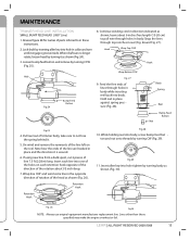
...). 3. Retention Hook Retention Hook Wire Reel Fig. 26 Fig.30 NOTE: Always use original equipment manufacturer replacement line. LEHR | ALL RIGHT RESERVED 2008-2009 15 If using new line from a bulk spool, cut 2 pieces of the line left on each line into hole tighten by turning CW (Fig. 29). Continue winding cord in the opposite direction of rotation of the head as shown (Fig. 30...
...). 3. Retention Hook Retention Hook Wire Reel Fig. 26 Fig.30 NOTE: Always use original equipment manufacturer replacement line. LEHR | ALL RIGHT RESERVED 2008-2009 15 If using new line from a bulk spool, cut 2 pieces of the line left on each line into hole tighten by turning CW (Fig. 29). Continue winding cord in the opposite direction of rotation of the head as shown (Fig. 30...
Operation Manual
Page 16
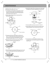
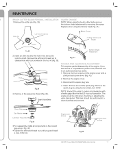
... your model is a curved shaft, loosen by turning head as shown for curved shaft and opposite for straight shaft. Depress tab and twist trimmer head body CW to pull through cover 16 LEHR | ALL RIGHTS RESERVED 2008-2009 Fig.3 7 Turn CCW until "click" (Fig. 36). Snap the free length of the rotation about 1/2 in reel and pull through holes trimmer head body (Fig. 34). MAINTENANCE TRIMMER HEAD LINE INSTALLATION LARGE BUMP FEED HEAD (.095" Line...
... your model is a curved shaft, loosen by turning head as shown for curved shaft and opposite for straight shaft. Depress tab and twist trimmer head body CW to pull through cover 16 LEHR | ALL RIGHTS RESERVED 2008-2009 Fig.3 7 Turn CCW until "click" (Fig. 36). Snap the free length of the rotation about 1/2 in reel and pull through holes trimmer head body (Fig. 34). MAINTENANCE TRIMMER HEAD LINE INSTALLATION LARGE BUMP FEED HEAD (.095" Line...
Operation Manual
Page 17
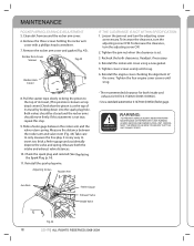
... the tool kit (Fig. 39). NOTE: When using the brush cutter blade remove the bottom shield attachment by using line trimmer head (Fig. 41). Cotter Pin Left-Hand Thread Nut Screw Cutting Attachment Sheild Loosen Fig. 38 Bottom Shield Attachment 2. Fig. 41 ROCKER ARM CLEARANCE ADJUSTMENT This requires partial disassembly of operation. Hole 2. This task should be cold when checking or adjusting the valve clearances. Remove the engine cover. 3. Fig.39 3. Remove in a clean dust free environment. Clean dirt...
... the tool kit (Fig. 39). NOTE: When using the brush cutter blade remove the bottom shield attachment by using line trimmer head (Fig. 41). Cotter Pin Left-Hand Thread Nut Screw Cutting Attachment Sheild Loosen Fig. 38 Bottom Shield Attachment 2. Fig. 41 ROCKER ARM CLEARANCE ADJUSTMENT This requires partial disassembly of operation. Hole 2. This task should be cold when checking or adjusting the valve clearances. Remove the engine cover. 3. Fig.39 3. Remove in a clean dust free environment. Clean dirt...
Operation Manual
Page 18
..., (This position is known as necessary. Check the spark plug and reinstall (See Replacing the Spark Plug (p.14). 11. Tighten the four engine cover screws until snug. 6. MAINTENANCE ROCKER ARM CLEARANCE ADJUSTMENT 5. Clean dirt from around the rocker arm cover. 6. Pull the starter rope slowly to bring the piston to only measure the free play. Readjust if necessary. 4. WARNING: TO PREVENT SERIOUS INJURY, NEVER PERFORM MAINTENANCE OR REPAIRS WITH UNIT RUNNING.
..., (This position is known as necessary. Check the spark plug and reinstall (See Replacing the Spark Plug (p.14). 11. Tighten the four engine cover screws until snug. 6. MAINTENANCE ROCKER ARM CLEARANCE ADJUSTMENT 5. Clean dirt from around the rocker arm cover. 6. Pull the starter rope slowly to bring the piston to only measure the free play. Readjust if necessary. 4. WARNING: TO PREVENT SERIOUS INJURY, NEVER PERFORM MAINTENANCE OR REPAIRS WITH UNIT RUNNING.
Operation Manual
Page 19
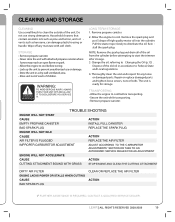
... plastic housing or handle. Allow the engine to Federal, State and Local regulations. 4. Do not use or damage. • Store the unit in accordance to cool. Wipe o any loose or damaged parts. Rein stall the spark plug. Thoroughly clean the unit and inspect for storage. Pull the starter rope slowly to start the trimmer after storage. 3. NOTE: Remove the spark plug and drain all of high quality motor oil into...
... plastic housing or handle. Allow the engine to Federal, State and Local regulations. 4. Do not use or damage. • Store the unit in accordance to cool. Wipe o any loose or damaged parts. Rein stall the spark plug. Thoroughly clean the unit and inspect for storage. Pull the starter rope slowly to start the trimmer after storage. 3. NOTE: Remove the spark plug and drain all of high quality motor oil into...

Operation Manual
Page 20
...IDLE SPEED IGNITION TYPE IGNITION SWITCH VALVE CLEARANCE SPARK PLUG GAP LUBRICATION CRANKCASE OIL CAPACITY FUEL CARBURETOR STARTER MUFFLER THROTTLE DRIVE SHAFT AND HOUSING DRIVE SHAFT HOUSING THROTTLE CONTROL APPROXIMATE UNIT WEIGHT CUTTING MECHANISM LINE SPOOL DIAMETER TRIMMING LINE DIAMETER CUTTING PATH DIAMETER AIR COOLED 4-CYCLE 25.4 CC CENTRIFUGAL 6,800-9300 R.P.M. 3,000-3,400 R.P.M. ELECTRONIC PUSH ON/OFF SWITCH 0.076-0.152MM (0.003-0.006 IN) 0.020 INCH (0.5 MM) SAE 10W-30 OIL 1.7 FLUIDOZ. (50mL) PROPANE 16.4OZ CANISTER CHOKE-LESS, ALL-POSITION AUTO REWIND BAFFLED WITH GUARD SAFETY LOCK...
...IDLE SPEED IGNITION TYPE IGNITION SWITCH VALVE CLEARANCE SPARK PLUG GAP LUBRICATION CRANKCASE OIL CAPACITY FUEL CARBURETOR STARTER MUFFLER THROTTLE DRIVE SHAFT AND HOUSING DRIVE SHAFT HOUSING THROTTLE CONTROL APPROXIMATE UNIT WEIGHT CUTTING MECHANISM LINE SPOOL DIAMETER TRIMMING LINE DIAMETER CUTTING PATH DIAMETER AIR COOLED 4-CYCLE 25.4 CC CENTRIFUGAL 6,800-9300 R.P.M. 3,000-3,400 R.P.M. ELECTRONIC PUSH ON/OFF SWITCH 0.076-0.152MM (0.003-0.006 IN) 0.020 INCH (0.5 MM) SAE 10W-30 OIL 1.7 FLUIDOZ. (50mL) PROPANE 16.4OZ CANISTER CHOKE-LESS, ALL-POSITION AUTO REWIND BAFFLED WITH GUARD SAFETY LOCK...

Operation Manual
Page 21
... this warranty does not cover tune-ups, spark plugs, carburetor adjustments, lters, cutting line, bump knobs, outer spools, inner reels, starter pulley, or rotating head parts that are included in your local authorized service dealer. Such use will wear and require replacement with respect to Subsection (4) below. Add-on or modi ed part. LEHR | ALL RIGHTS RESERVED 2008-2009 21 Additionally, this operator's manual. HOW TO OBTAI N S ERVICE: Warranty service is to the owner...
... this warranty does not cover tune-ups, spark plugs, carburetor adjustments, lters, cutting line, bump knobs, outer spools, inner reels, starter pulley, or rotating head parts that are included in your local authorized service dealer. Such use will wear and require replacement with respect to Subsection (4) below. Add-on or modi ed part. LEHR | ALL RIGHTS RESERVED 2008-2009 21 Additionally, this operator's manual. HOW TO OBTAI N S ERVICE: Warranty service is to the owner...


