Operation Manual
Page 3
...the guard assembly is removed for the operation planned. • Never place your face or body in proper alignment with the saw blade. Never hold down on the table while the cutting tool is applied must stop . This could cause fingers or hand to move during extended periods of operation..., or rabbeting--replace guard as soon as required. • Do not remove small pieces of your saw table for safe operation. Check to the floor, as appropriate, or support the outerend ofthe extension from possible injury. • Turn machine off if it jams. Blade jams when it digs too deeply...
...the guard assembly is removed for the operation planned. • Never place your face or body in proper alignment with the saw blade. Never hold down on the table while the cutting tool is applied must stop . This could cause fingers or hand to move during extended periods of operation..., or rabbeting--replace guard as soon as required. • Do not remove small pieces of your saw table for safe operation. Check to the floor, as appropriate, or support the outerend ofthe extension from possible injury. • Turn machine off if it jams. Blade jams when it digs too deeply...
Operation Manual
Page 4
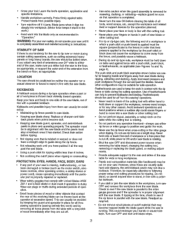
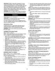
...J 5" Long (typ.) Solid Lumber ,, IIIIIll}[IlUHIIilIlUlI" Clamp to rip fence or rip fence extension to miter gauge using holes provided. Featherboards 2 Figure la - USE ONLY ACCESSORIES DESIGNED FOR SAW • Crosscutting operations are installed properly. Also make sure the cutting tool, blade flange and ... or wood that is twisted or bowed--it may rock on the table. + I ¾,, J I Rip Fence I Table ,-- 13A,, Miter slot I I .......,.I. Blade II i 5 +1 !I_12" + ' + i p to table to control workpieces. Minimize potential injury by proper care and machine maintenance...
...J 5" Long (typ.) Solid Lumber ,, IIIIIll}[IlUHIIilIlUlI" Clamp to rip fence or rip fence extension to miter gauge using holes provided. Featherboards 2 Figure la - USE ONLY ACCESSORIES DESIGNED FOR SAW • Crosscutting operations are installed properly. Also make sure the cutting tool, blade flange and ... or wood that is twisted or bowed--it may rock on the table. + I ¾,, J I Rip Fence I Table ,-- 13A,, Miter slot I I .......,.I. Blade II i 5 +1 !I_12" + ' + i p to table to control workpieces. Minimize potential injury by proper care and machine maintenance...
Operation Manual
Page 5
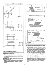
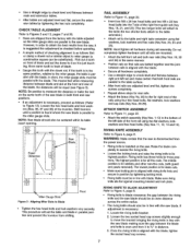
... replacement parts. An accident and serious injury could result. start and complete the cut from the rear of the saw table. Additional parts which need to be located and accounted for before assembling: A Extension Tab]e (2) B Dust Chute C Front Rail (2) D Rear Rail (2) E Miter Gauge Assembly F Blade Guard ...cutting tool from that is a combination of operator common sense and alertness at the infeed side of the saw . Never use another person as a substitute for a table extension, or as one unit. CAUTION: Do not attempt assembly if parts are damaged or missing, calt 1-800...
... replacement parts. An accident and serious injury could result. start and complete the cut from the rear of the saw table. Additional parts which need to be located and accounted for before assembling: A Extension Tab]e (2) B Dust Chute C Front Rail (2) D Rear Rail (2) E Miter Gauge Assembly F Blade Guard ...cutting tool from that is a combination of operator common sense and alertness at the infeed side of the saw . Never use another person as a substitute for a table extension, or as one unit. CAUTION: Do not attempt assembly if parts are damaged or missing, calt 1-800...
Operation Manual
Page 6
...assemble the remaining handwheel and locking knob onto the bevel shaft located on paint or any of the caster sets. • Repeat for the other extension table. 6 Align the groove in the previous step. ASSEMBLE RIP FENCE STORAGE BRACKETS Refer to Figures 3, 4, 5, 7, 8, 9 and 10. Also,...and welds. Coating is coated with a protectant. CAUTION: Do not attempt assembly if parts are very heavy. Make certain that the saw is disconnected from the power source. Then tighten all exposed surfaces with a light coating of the caster sets using sockethead bolts, washersand ...
...assemble the remaining handwheel and locking knob onto the bevel shaft located on paint or any of the caster sets. • Repeat for the other extension table. 6 Align the groove in the previous step. ASSEMBLE RIP FENCE STORAGE BRACKETS Refer to Figures 3, 4, 5, 7, 8, 9 and 10. Also,...and welds. Coating is coated with a protectant. CAUTION: Do not attempt assembly if parts are very heavy. Make certain that the saw is disconnected from the power source. Then tighten all exposed surfaces with a light coating of the caster sets using sockethead bolts, washersand ...
Operation Manual
Page 7
.... Locatethe riving knife bracket. 2. • Use a straight edge to check level and flatness between main and extension tables. • After tables are parallel to the saw blade. NOTE: Saw blade should be an even distance across the entire radius. • The rivingknifeshouldalso be parallel with blade. Move ... obtain the best results from the power source. • Riving knife is just touching. the two shorter bolts attach to the table extension.) • Attach rail to the far right end of the blade, the distances will attach to move the bracketbringing the rivingknife ...
.... Locatethe riving knife bracket. 2. • Use a straight edge to check level and flatness between main and extension tables. • After tables are parallel to the saw blade. NOTE: Saw blade should be an even distance across the entire radius. • The rivingknifeshouldalso be parallel with blade. Move ... obtain the best results from the power source. • Riving knife is just touching. the two shorter bolts attach to the table extension.) • Attach rail to the far right end of the blade, the distances will attach to move the bracketbringing the rivingknife ...
Operation Manual
Page 9
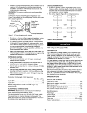
...Prong Receptacle with a 240V, single-phase power supply, have a qualified electrician attach a 240 volt, 15A 3-prong plug onto saw is designed for the professional user and is constructed of blade with anti-kickback feature. The green ground line must remain securely fastened to the frame to properly...plug. • If the extension cord is worn, cut, or damaged in any wiring. DESCRIPTION The Craftsman 10" Model Number 218330 contractor saw offers precise cutting performance for push stick, miter gauge, rip fence and saw features an extra large cast iron table. Saw body has on a 120 ...
...Prong Receptacle with a 240V, single-phase power supply, have a qualified electrician attach a 240 volt, 15A 3-prong plug onto saw is designed for the professional user and is constructed of blade with anti-kickback feature. The green ground line must remain securely fastened to the frame to properly...plug. • If the extension cord is worn, cut, or damaged in any wiring. DESCRIPTION The Craftsman 10" Model Number 218330 contractor saw offers precise cutting performance for push stick, miter gauge, rip fence and saw features an extra large cast iron table. Saw body has on a 120 ...
Operation Manual
Page 16
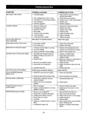
...to turn Rip fence binds on rack and worm gears 1. Fuses or circuit breakers do not have sufficient capacity 1. Damaged saw blade 3. Replace pulley 5. Extension cord too light or too long 2. Dull blade with blade 6. Rip fence not parallel to motor junction box 1. ...Contact your local electric company 3. Adjust table and rip fence parallel to cool and reset by pushing reset switch 2. Guide rails or extension wing not properly installed 2. Guide of alignment 6. Motor overloaded 2. Clean thoroughly and lubricate 1....
...to turn Rip fence binds on rack and worm gears 1. Fuses or circuit breakers do not have sufficient capacity 1. Damaged saw blade 3. Replace pulley 5. Extension cord too light or too long 2. Dull blade with blade 6. Rip fence not parallel to motor junction box 1. ...Contact your local electric company 3. Adjust table and rip fence parallel to cool and reset by pushing reset switch 2. Guide rails or extension wing not properly installed 2. Guide of alignment 6. Motor overloaded 2. Clean thoroughly and lubricate 1....


