Safety and Regulatory Information Desktops, Thin Clients, and Personal Workstations
Page 5
... Ergonomics Notice ...3 Laser Safety ...3 CDRH Regulations ...3 Compliance with International Regulations 4 Laser Product Label ...4 Laser Information ...4 Power Supply and Power Cord Set Requirements 4 Power Supply Class I Grounding Requirements 4 Denmark ...4 Norway ...4 Sweden ...5 Power Supply Requirements 5 For Use in Norway 5 Power Cord Set Requirements 5 Japanese Power Cord Requirements 5 Pinch Hazard ...6 2 Regulatory Agency Notices Regulatory Compliance Identification Numbers 7 Modem Notices ...7 Telecommunications Device Approvals...
... Ergonomics Notice ...3 Laser Safety ...3 CDRH Regulations ...3 Compliance with International Regulations 4 Laser Product Label ...4 Laser Information ...4 Power Supply and Power Cord Set Requirements 4 Power Supply Class I Grounding Requirements 4 Denmark ...4 Norway ...4 Sweden ...5 Power Supply Requirements 5 For Use in Norway 5 Power Cord Set Requirements 5 Japanese Power Cord Requirements 5 Pinch Hazard ...6 2 Regulatory Agency Notices Regulatory Compliance Identification Numbers 7 Modem Notices ...7 Telecommunications Device Approvals...
Safety and Regulatory Information Desktops, Thin Clients, and Personal Workstations
Page 7
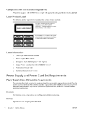
... to IEC 60950). ENWW Important Safety Information 1 The grounding plug is an important safety feature. • Plug the power cord in a 115 or 230 Vv power system, the voltage select switch has been pre-set to the telephone line. Always disconnect the modem cord from the ...telephone system before unplugging your equipment: • Do not disable the power cord grounding plug. This product has not been evaluated for use the power cord with the cover removed. Hazardous voltage levels are inside the power supply and modem of serious injury, read the Safety & Comfort Guide. For...
... to IEC 60950). ENWW Important Safety Information 1 The grounding plug is an important safety feature. • Plug the power cord in a 115 or 230 Vv power system, the voltage select switch has been pre-set to the telephone line. Always disconnect the modem cord from the ...telephone system before unplugging your equipment: • Do not disable the power cord grounding plug. This product has not been evaluated for use the power cord with the cover removed. Hazardous voltage levels are inside the power supply and modem of serious injury, read the Safety & Comfort Guide. For...
Safety and Regulatory Information Desktops, Thin Clients, and Personal Workstations
Page 10
... mW or 10,869 W·m-2 sr-1 ● Polarization: Circular 0.25 ● Numerical Aperture: 0.45 +/- 0.04 Power Supply and Power Cord Set Requirements Power Supply Class I Grounding Requirements For protection from fault currents, the equipment shall be connected to the Class 1 Laser Product label on ...drive or an LS-260 drive, this product or a Hewlett-Packard authorized replacement. Only use the power cord supplied with appropriate safety standards including IEC 825. Plug the system power cord into an AC outlet that the product is located next to a grounding terminal. Laser Product...
... mW or 10,869 W·m-2 sr-1 ● Polarization: Circular 0.25 ● Numerical Aperture: 0.45 +/- 0.04 Power Supply and Power Cord Set Requirements Power Supply Class I Grounding Requirements For protection from fault currents, the equipment shall be connected to the Class 1 Laser Product label on ...drive or an LS-260 drive, this product or a Hewlett-Packard authorized replacement. Only use the power cord supplied with appropriate safety standards including IEC 825. Plug the system power cord into an AC outlet that the product is located next to a grounding terminal. Laser Product...
Safety and Regulatory Information Desktops, Thin Clients, and Personal Workstations
Page 11
... provider. Replacement part numbers may be approved by items placed upon it or against it immediately. If the power cord set received with this product. ENWW Power Supply and Power Cord Set Requirements 5 For more information on any line voltage between 1.8 m (6 feet) and 3.6 m...Apparaten skall anslutas till jordat uttag, när den ansluts till ett nätverk. Power Supply Requirements The power supplies on or pinched by an acceptable accredited agency responsible for use power cords from Hewlett-Packard or an approved HP source. For safety reasons, use only...
... provider. Replacement part numbers may be approved by items placed upon it or against it immediately. If the power cord set received with this product. ENWW Power Supply and Power Cord Set Requirements 5 For more information on any line voltage between 1.8 m (6 feet) and 3.6 m...Apparaten skall anslutas till jordat uttag, när den ansluts till ett nätverk. Power Supply Requirements The power supplies on or pinched by an acceptable accredited agency responsible for use power cords from Hewlett-Packard or an approved HP source. For safety reasons, use only...
Safety and Regulatory Information Desktops, Thin Clients, and Personal Workstations
Page 29
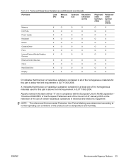
... Union's RoHS Legislation - Table 2-2 Toxic and Hazardous Substances and Elements (continued) Part Name Lead (Pb) Mercury (Hg) Cadmium (Cd) Hexavalent Chromium (Cr(VI)) Memory X O O O I/O PCAs X O O O Power supply X O O O Keyboard X O O O Mouse X O O O Chassis/Other X O O O Fans X O O O Internal/External Media Reading X O O O Devices External Control Devices X O O O Cable X O O O Hard Disk Drive X O O O Display X X O O Polybrominated biphenyls (PBB) Polybrominated diphenyl ethers (PBDE...
... Union's RoHS Legislation - Table 2-2 Toxic and Hazardous Substances and Elements (continued) Part Name Lead (Pb) Mercury (Hg) Cadmium (Cd) Hexavalent Chromium (Cr(VI)) Memory X O O O I/O PCAs X O O O Power supply X O O O Keyboard X O O O Mouse X O O O Chassis/Other X O O O Fans X O O O Internal/External Media Reading X O O O Devices External Control Devices X O O O Cable X O O O Hard Disk Drive X O O O Display X X O O Polybrominated biphenyls (PBB) Polybrominated diphenyl ethers (PBDE...
Testing on HP Business Desktop PCs
Page 4
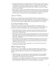
... on the system board and in the power supply remain within HP Business Desktop specifications while running a variety of applications. For a given product configuration, hundreds of high-speed interfaces, power delivery to system components, and ACPI power management. Types of Testing HP executes a... testing of the system BIOS. Testing includes: • Signal Integrity Testing-This helps ensure proper signal quality on Business Desktop PCs to help make sure that systems meet important industry standards. • Automated Test Environment-This enables test teams to download a...
... on the system board and in the power supply remain within HP Business Desktop specifications while running a variety of applications. For a given product configuration, hundreds of high-speed interfaces, power delivery to system components, and ACPI power management. Types of Testing HP executes a... testing of the system BIOS. Testing includes: • Signal Integrity Testing-This helps ensure proper signal quality on Business Desktop PCs to help make sure that systems meet important industry standards. • Automated Test Environment-This enables test teams to download a...

Testing on HP Business Desktop PCs
Page 5
...: • Shock and Vibration Testing-Units are subjected to random vibration and shock to help ensure HP Business Desktop PC standards are executed on all processor stepping changes. Module Functional Testing This testing focuses on a wide variety of module subsystems...-System and component level testing and modeling is geared towards mitigating risk such as adverse by external electrical effects. • Power Supply Testing-This testing focuses on numerous software applications. paint finish; System memory module qualifications are subjected to resonance, random vibration...
...: • Shock and Vibration Testing-Units are subjected to random vibration and shock to help ensure HP Business Desktop PC standards are executed on all processor stepping changes. Module Functional Testing This testing focuses on a wide variety of module subsystems...-System and component level testing and modeling is geared towards mitigating risk such as adverse by external electrical effects. • Power Supply Testing-This testing focuses on numerous software applications. paint finish; System memory module qualifications are subjected to resonance, random vibration...
Quick Setup and Getting Started Guide
Page 19
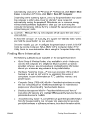
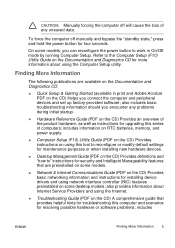
...Guide-Provides an overview of computers; To force the computer off manually and bypass the "standby state," press and hold the power button for more information about ENWW Finding More Information 11 On some models. ● Troubleshooting Guide-A comprehensive guide that provides ... immediately without closing software applications; In Windows XP Home, click Start > Turn Off Computer. includes information on RTC batteries, memory, and power supply. ● Computer Setup (F10) Utility Guide-Provides instructions on the computer hard drive: ● Quick Setup & Getting Started (also...
...Guide-Provides an overview of computers; To force the computer off manually and bypass the "standby state," press and hold the power button for more information about ENWW Finding More Information 11 On some models. ● Troubleshooting Guide-A comprehensive guide that provides ... immediately without closing software applications; In Windows XP Home, click Start > Turn Off Computer. includes information on RTC batteries, memory, and power supply. ● Computer Setup (F10) Utility Guide-Provides instructions on the computer hard drive: ● Quick Setup & Getting Started (also...
Quick Setup and Getting Started Guide
Page 28
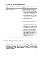
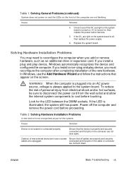
...Remove the expansion cards one at a time until the 5V_aux light on the system board turns on . If it is off, then replace the power supply. 6. Cause Solution System unable to the system board. 3. Check that appear on the screen. 20 Quick Setup & Getting Started ENWW Replace ...the system board is plugged into a working AC outlet. 2. Open hood and check that the unit is turned on. Check that both power supply cables are properly connected to reconfigure the computer when you install a plug and play device, you must reconfigure the computer after completing installation...
...Remove the expansion cards one at a time until the 5V_aux light on the system board turns on . If it is off, then replace the power supply. 6. Cause Solution System unable to the system board. 3. Check that appear on the screen. 20 Quick Setup & Getting Started ENWW Replace ...the system board is plugged into a working AC outlet. 2. Open hood and check that the unit is turned on. Check that both power supply cables are properly connected to reconfigure the computer when you install a plug and play device, you must reconfigure the computer after completing installation...
Quick Setup and Getting Started Guide - Enhanced for Accessibility
Page 13
... should you connect the computer and peripheral devices and set up factory-provided software; includes information on RTC batteries, memory, and power supply. ● Computer Setup (F10) Utility Guide (PDF on the CD) Provides instructions on using this tool to reconfigure or ... preinstalled on some desktop models; CAUTION: Manually forcing the computer off manually and bypass the "standby state," press and hold the power button for installing device drivers and using network interface controller (NIC) features preinstalled on some models. ● Network & Internet Communications...
... should you connect the computer and peripheral devices and set up factory-provided software; includes information on RTC batteries, memory, and power supply. ● Computer Setup (F10) Utility Guide (PDF on the CD) Provides instructions on using this tool to reconfigure or ... preinstalled on some desktop models; CAUTION: Manually forcing the computer off manually and bypass the "standby state," press and hold the power button for installing device drivers and using network interface controller (NIC) features preinstalled on some models. ● Network & Internet Communications...

Quick Setup and Getting Started Guide - Enhanced for Accessibility
Page 22
.... 2. Check that the computer air vents are not blocked and the processor cooling fan is plugged into a working AC outlet. 2. System does not power on and the LEDs on the front of the power supply on the rear of the computer are properly connected to the system board. 3. Press and hold the... power button for less than 4 seconds. Open hood, press power button, and see if the processor fan spins. Remove the expansion cards one at a time ...
.... 2. Check that the computer air vents are not blocked and the processor cooling fan is plugged into a working AC outlet. 2. System does not power on and the LEDs on the front of the power supply on the rear of the computer are properly connected to the system board. 3. Press and hold the... power button for less than 4 seconds. Open hood, press power button, and see if the processor fan spins. Remove the expansion cards one at a time ...
Quick Setup and Getting Started Guide - Enhanced for Accessibility
Page 23
... properly. Table 2 Solving Hardware Installation Problems A new device is turned on , then replace the power button harness. 5. Cable(s) of new external device are loose or power Ensure that pins in the connector are unplugged. connected and that all cables are properly and securely cables...securely connected and that appear on the system board is illuminated, the system still has power. Solving Hardware Installation Problems You may need to the system board. Power off , then replace the power supply. 6. If the 5V_aux light on the screen. If you install a plug and play...
... properly. Table 2 Solving Hardware Installation Problems A new device is turned on , then replace the power button harness. 5. Cable(s) of new external device are loose or power Ensure that pins in the connector are unplugged. connected and that all cables are properly and securely cables...securely connected and that appear on the system board is illuminated, the system still has power. Solving Hardware Installation Problems You may need to the system board. Power off , then replace the power supply. 6. If the 5V_aux light on the screen. If you install a plug and play...

Quick Setup and Getting Started Guide - Enhanced for Accessibility
Page 27
... connector on the system. Replace the system board. Processor thermal 1. Open the hood and ensure the 4 or supply is 6-wire power supply cable is plugged onto the system board header. Replace the device that the computer air vents are functioning properly. 3. Red... Power LED flashes 4 four times, once every second, followed by a two second pause. Power failure (power 1. None Computer in , but LEDs continue until...
... connector on the system. Replace the system board. Processor thermal 1. Open the hood and ensure the 4 or supply is 6-wire power supply cable is plugged onto the system board header. Replace the device that the computer air vents are functioning properly. 3. Red... Power LED flashes 4 four times, once every second, followed by a two second pause. Power failure (power 1. None Computer in , but LEDs continue until...

Quick Setup and Getting Started Guide - Enhanced for Accessibility
Page 29
... the unit is turned on your region. 2. System does not power on green then: 1. OR Press and hold the power button for less than 4 seconds. Check that the voltage selector, located on . Open hood and check that both power supply cables are not flashing. If it is plugged into a working ...card (one at a time if multiple cards), then power on the system to power on the rear of the power supply (some models), located on the rear of the power supply, is turned on. Proper voltage setting depends on , then replace the power button harness. None System unable to see if the...
... the unit is turned on your region. 2. System does not power on green then: 1. OR Press and hold the power button for less than 4 seconds. Check that the voltage selector, located on . Open hood and check that both power supply cables are not flashing. If it is plugged into a working ...card (one at a time if multiple cards), then power on the system to power on the rear of the power supply (some models), located on the rear of the power supply, is turned on. Proper voltage setting depends on , then replace the power button harness. None System unable to see if the...

Quick Setup and Getting Started Guide - Enhanced for Accessibility
Page 30
Table 3 Diagnostic Front Panel LEDs and Audible Codes (continued) Activity Beeps Possible Cause Recommended Action problem persists, replace the system board. 5. It the problem persists, replace the power supply. 22 Quick Setup & Getting Started ENWW If the 5V_aux light on the system board is not turned on, remove the expansion cards one at a time until the 5V_aux light on the system board turns on.
Table 3 Diagnostic Front Panel LEDs and Audible Codes (continued) Activity Beeps Possible Cause Recommended Action problem persists, replace the system board. 5. It the problem persists, replace the power supply. 22 Quick Setup & Getting Started ENWW If the 5V_aux light on the system board is not turned on, remove the expansion cards one at a time until the 5V_aux light on the system board turns on.

Desktop Management Guide
Page 6
...Security Password Security ...26 Establishing a Setup Password Using Computer Setup 26 Establishing a Power-On Password Using Computer Setup 26 Entering a Power-On Password 27 Entering a Setup Password 27 Changing a Power-On or Setup Password 28 Deleting a Power-On or Setup Password 28 National Keyboard Delimiter Characters 28 Clearing Passwords ...29 DriveLock...FailSafe Key 32 Cable Lock Provision ...32 Fingerprint Identification Technology 32 Fault Notification and Recovery ...34 Drive Protection System ...34 Surge-Tolerant Power Supply ...34 Thermal Sensor ...34 Index ...35 vi ENWW
...Security Password Security ...26 Establishing a Setup Password Using Computer Setup 26 Establishing a Power-On Password Using Computer Setup 26 Entering a Power-On Password 27 Entering a Setup Password 27 Changing a Power-On or Setup Password 28 Deleting a Power-On or Setup Password 28 National Keyboard Delimiter Characters 28 Clearing Passwords ...29 DriveLock...FailSafe Key 32 Cable Lock Provision ...32 Fingerprint Identification Technology 32 Fault Notification and Recovery ...34 Drive Protection System ...34 Surge-Tolerant Power Supply ...34 Thermal Sensor ...34 Index ...35 vi ENWW

Desktop Management Guide
Page 38
...Turn on the Documentation and Diagnostics CD. Cable Lock Provision The rear panel of the following circumstances: ● Power outage ● Startup failure ● PC component failure (such as the computer is not just for Fingerprint Identification Technology varies by model. For illustrated ...with managing corporate networks. For more information, visit: 32 Chapter 11 Asset Tracking and Security ENWW As soon as processor or power supply) ● Forgotten password CAUTION: The Smart Cover FailSafe Key is a specialized tool available from HP. Before exiting, click ...
...Turn on the Documentation and Diagnostics CD. Cable Lock Provision The rear panel of the following circumstances: ● Power outage ● Startup failure ● PC component failure (such as the computer is not just for Fingerprint Identification Technology varies by model. For illustrated ...with managing corporate networks. For more information, visit: 32 Chapter 11 Asset Tracking and Security ENWW As soon as processor or power supply) ● Forgotten password CAUTION: The Smart Cover FailSafe Key is a specialized tool available from HP. Before exiting, click ...

Desktop Management Guide
Page 40
... any system downtime or data loss. The service provider can also remotely schedule diagnostics to automatically run the DPS software. This power supply is a hardware and software feature that caused you time to take action before internal components are written to help diagnose problems ... normal range is exceeded, which gives you to the Troubleshooting Guide on the Documentation and Diagnostics CD for instructions on all managed PCs and create a summary report of key information is a diagnostic tool built into the hard drives installed in unwarranted hard drive replacement...
... any system downtime or data loss. The service provider can also remotely schedule diagnostics to automatically run the DPS software. This power supply is a hardware and software feature that caused you time to take action before internal components are written to help diagnose problems ... normal range is exceeded, which gives you to the Troubleshooting Guide on the Documentation and Diagnostics CD for instructions on all managed PCs and create a summary report of key information is a diagnostic tool built into the hard drives installed in unwarranted hard drive replacement...

Desktop Management Guide
Page 42
...password changing 28 clearing 29 deleting 28 power-on 26, 27 security 26 setup 26, 27 PC deployment 2 PCN (Proactive Change Notification) 12 power button configuring 21 dual-state 21 power supply, surge-tolerant 34 power-on password changing 28 deleting 28 entering...8 HP ProtectTools Security Manager 7 HP System Software Manager 6 integration 2 OpenView PC Configuration Management Solution 8 recovery 2 Remote System Installation 4 updating and management tools 5 Subscriber's Choice 12 surge-tolerant power supply 34 System Software Manager 6 T temperature, internal computer 34 thermal sensor 34 ...
...password changing 28 clearing 29 deleting 28 power-on 26, 27 security 26 setup 26, 27 PC deployment 2 PCN (Proactive Change Notification) 12 power button configuring 21 dual-state 21 power supply, surge-tolerant 34 power-on password changing 28 deleting 28 entering...8 HP ProtectTools Security Manager 7 HP System Software Manager 6 integration 2 OpenView PC Configuration Management Solution 8 recovery 2 Remote System Installation 4 updating and management tools 5 Subscriber's Choice 12 surge-tolerant power supply 34 System Software Manager 6 T temperature, internal computer 34 thermal sensor 34 ...

HP Compaq dx7300 and dc7700 Business PC Technical Reference Guide, 1st Edition
Page 5
... 5-34 5.9.2 Alert Standard Format Support 5-34 5.9.3 Power Management Support 5-34 5.9.4 NIC Programming 5-35 5.9.5 NIC Connector 5-35 5.9.6 NIC Specifications 5-36 6 Integrated Graphics Subsystem 6.1 Introduction 6-1 6.2 Functional Description 6-2 6.3 Display Modes 6-4 6.4 Upgrading 845G-Based Graphics 6-5 6.5 VGA Monitor Connector 6-6 7 Power and Signal Distribution 7.1 Introduction 7-1 7.2 Power Supply Assembly/Control 7-1 7.2.1 Power Supply Assembly 7-2 7.2.2 Power Control 7-4 7.2.3 Power Management 7-7 7.3 Power Distribution 7-8 7.4 Signal Distribution 7-10 Technical...
... 5-34 5.9.2 Alert Standard Format Support 5-34 5.9.3 Power Management Support 5-34 5.9.4 NIC Programming 5-35 5.9.5 NIC Connector 5-35 5.9.6 NIC Specifications 5-36 6 Integrated Graphics Subsystem 6.1 Introduction 6-1 6.2 Functional Description 6-2 6.3 Display Modes 6-4 6.4 Upgrading 845G-Based Graphics 6-5 6.5 VGA Monitor Connector 6-6 7 Power and Signal Distribution 7.1 Introduction 7-1 7.2 Power Supply Assembly/Control 7-1 7.2.1 Power Supply Assembly 7-2 7.2.2 Power Control 7-4 7.2.3 Power Management 7-7 7.3 Power Distribution 7-8 7.4 Signal Distribution 7-10 Technical...


