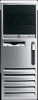
HP Compaq dx7300 and dc7700 Business PC Technical Reference Guide, 1st Edition
Page 28
...Layout, Left Side View 2-12 www.hp.com Technical Reference Guide Features include: ■ Externally accessible drive bay assembly. ■ Easy access to expansion slots and all socketed system board components. 1 23 4 5 6 q - 9 7 8 Item 1 2 3 4 Description Power supply assembly Processor ...Externally accessible drive bays 6 Internally accessible drive bays Item 7 8 9 10 11 Description Speaker PCI 2.3 slots PCI Express x1 slot PCI Express x16 graphics/normal-layout SDVO slot [1] Chassis fan -- -- NOTE: [1] Accepts PCI-E graphics or normal-layout ADD2 card. Figure 2-8....
HP Compaq dx7300 and dc7700 Business PC Technical Reference Guide, 1st Edition
Page 29
... may be configured for HP Compaq dc7700 models. CMT Chassis Layout, Left Side View (Minitower configuration) Technical Reference Guide www.hp.com 2-13 Figure 2-9. System Overview Convertible Minitower Figure 2-9 shows the layout for the Convertible Minitower (CMT) chassis in the minitower configuration used for minitower (vertical) or desktop (horizontal) position. ■ Easy access to expansion slots and all socketed system board...
Hardware Reference Guide - dc7700 CMT
Page 27
... x1 expansion slot and one PCI Express x16 expansion slot. To remove, replace, or add an expansion card: 1. Disconnect the power cord from the computer. 3. Removing or Installing an Expansion Card The computer has two standard full-height PCI expansion slots that prohibit opening the computer. 2. Figure 2-9 Expansion Slot Locations Item Description 1 PCI expansion slot 2 PCI expansion slot 3 PCI Express x1 expansion slot 4 PCI Express x16 expansion slot...
Hardware Reference Guide - dc7700 CMT
Page 28
If the LED is plugged into an active AC outlet. Locate the correct vacant expansion socket on the system board and the corresponding expansion slot on the back of the power-on state, voltage is always present on the system board as long as ... the computer. 5. Remove the computer access panel. Before installing an expansion card, remove the expansion slot cover or the existing expansion card. 22 Chapter 2 Hardware Upgrades ENWW CAUTION Regardless of the computer chassis. 7. Figure 2-10 Opening the Expansion Slot Retainer 8. CAUTION After removing the access panel, look for the LED...
Hardware Reference Guide - dc7700 CMT
Page 29
...straight up to remove it back and forth until the connectors pull free from the expansion slot. Figure 2-11 Removing an Expansion Slot Cover b. Lift the expansion slot cover from the socket. NOTE Before removing an installed expansion card, disconnect any cables that may be attached to scrape the card against other ... are removing a standard PCI card, hold the card at each end and carefully rock it . If you are installing an expansion card in a vacant socket, remove the appropriate expansion slot cover on the back of the chassis. Figure 2-12 Removing a Standard PCI...
Hardware Reference Guide - dc7700 CMT
Page 30
... Store the removed card in anti-static packaging. 10. Lift the card straight up to remove it with a new card or expansion slot cover for proper cooling of the expansion socket away from the card and carefully rock the card back and forth until the connectors pull free from the socket. If... you are not installing a new expansion card, install an expansion slot cover to scrape the card against other components. If you are removing a PCI Express x16 card, pull the retention arm on the...
Hardware Reference Guide - dc7700 CMT
Page 59
...drives connecting cables 29 installing 29 locations 26 removing 27 E electrostatic discharge, preventing damage 49 expansion card installing 21 removing 21 slot locations 21 expansion slot cover removing 23 replacing 24 H hard drive installing 33 removing 27 restoring software 35 headphone ...Lock 10 M media card reader features 3 installing 30 removing 27 memory installing 17 populating sockets 18 specifications 17 microphone connector 2, 4 minitower conversion 38 monitor connector 4 mouse connector 4 special functions 7 N network connector 4 O optical drive cleaning 52 defined 2 installing ...
Hardware Reference Guide - dc7700 CMT
Page 60
R rear panel components 4 removing battery 43 bezel blanks 16 computer access panel 12 drives from drive bay 27 expansion card 21 expansion slot cover 23 front bezel 14 media card reader 27 PCI card 23 PCI Express card 24 Smart Cover Lock 10 S security cable lock 47 padlock 48 Smart Cover Lock 10 serial connector 4 serial number location 7 shipping preparation 52 Smart Cover Lock 10 specifications computer 41 memory 17 U unlocking access panel USB ports front panel 2 rear panel 4 10, 47 V ventilation guidelines 51 W Windows Logo key 6 54 Index ENWW
HP Compaq dc7700 Business Desktop PC Service Reference Guide, 1st Edition
Page 82
Removal and Replacement Procedures - Locate the correct vacant expansion socket on the system board and the corresponding expansion slot on . Convertible Minitower (CMT) Chassis ✎ The computer automatically recognizes the ...additional memory when the computer is turned on the back of the computer chassis. 4. Push down and out on the two green thumb tabs inside the chassis and rotate the expansion card retention latch up. 6-12 433612-001 Service Reference Guide, dc7700...
HP Compaq dc7700 Business Desktop PC Service Reference Guide, 1st Edition
Page 83
Convertible Minitower (CMT) Chassis 5. Lift the expansion card straight up to release it back and forth until the connectors pull free from the chassis frame. Pull the slot cover straight up to release it from the chassis frame. 6. If you are removing an expansion card from a standard expansion socket, hold the card at each end and carefully...
HP Compaq dc7700 Business Desktop PC Service Reference Guide, 1st Edition
Page 84
...a PCI Express card from a x16 PCI Express socket with a new card or expansion slot cover for proper cooling of the chassis to scrape the card against other components. 8. Lift the expansion card straight up then pull it with a retention mechanism, pull the retention arm.... 6-14 433612-001 Service Reference Guide, dc7700 If you are not installing a new expansion card, install an expansion slot cover to close the open slot and continue with step 12. Removal and Replacement Procedures - If you must replace it in anti-static packaging. 9. Convertible Minitower (CMT) Chassis 7.
HP Compaq dc7700 Business Desktop PC Service Reference Guide, 1st Edition
Page 85
Slide the bracket on the end of the expansion card down into the slot on the back of the chassis and press the card down firmly into place. 12. Replace the computer access panel. 14. If you ...board as needed. 13. Service Reference Guide, dc7700 433612-001 6-15 Reconfigure the computer, if necessary. Close the expansion slot latch, making sure that the whole connector seats properly in the expansion card socket on the Documentation and Diagnostics CD for instructions about using Computer Setup. Removal and Replacement Procedures - Convertible Minitower (CMT) Chassis 10.
HP Compaq dc7700 Business Desktop PC Service Reference Guide, 1st Edition
Page 86
Convertible Minitower (CMT) Chassis 6.11 PCI Retainer Latch 1. Remove the computer access panel (Section 6.5). 3. Locate the correct vacant expansion socket on the system board and the corresponding expansion slot on the broken plastic latches 1, then complete the removal by pulling the latches off the pivoting bar 2. 6-16 433612-001 Service Reference Guide, dc7700 Use a thin flat blade...
HP Compaq dc7700 Business Desktop PC Service Reference Guide, 1st Edition
Page 130
... latch on the back of internal components during operation. 7-16 433612-001 Service Reference Guide, dc7700 If you are not installing a new expansion card, install an expansion slot cover to secure the expansion cards and expansion slot covers. Ä CAUTION: All expansion card slots on x16 card socket only) and carefully rock the card back and forth until the...
HP Compaq dc7700 Business Desktop PC Service Reference Guide, 1st Edition
Page 131
... straight up and out of the chassis 2. Prepare the computer for disassembly (Section 7.1). 3. Service Reference Guide, dc7700 433612-001 7-17 Remove the computer cover (Section 7.5). 4. Remove all PCI and PCI Express expansion cards from the PCI expansion slots (Section 7.9). 5. Removal and Replacement Procedures- Remove the security clip (Section 7.4.1), rotate the power supply to its...
HP Compaq dc7700 Business Desktop PC Service Reference Guide, 1st Edition
Page 135
...backwall. Reconnect all power and data cables to the system board. 17. Install the power supply. Install the full-height PCI expansion card in the available slot in a previous step. Install the serial connector into the new backwall using the two screws that were removed from the serial ...system board sits properly over the locking pins. Service Reference Guide, dc7700 433612-001 7-21 Be sure to secure it to the system board. 19. Be sure the riser card in the cage is in the PCI expansion slot on the cage to use proper cable handling and placement precautions. ...
HP Compaq dc7700 Business Desktop PC Service Reference Guide, 1st Edition
Page 177
...3. If you are installing a new expansion card, continue with step 8. Ä CAUTION: After removing an expansion card, you are not installing a new expansion card, install an expansion slot cover to remove it firmly in anti-static packaging. 6. Service Reference Guide, dc7700 433612-001 8-15 Prepare the computer ... you must replace it back and forth until the connectors pull free from the cage. Remove the expansion card cage (Section 8.11). 4. Pull the expansion card straight out 3 to close the open slot and continue with step 5. Ultra-Slim Desktop (USDT) Chassis 8.12...
HP Compaq dc7700 Business Desktop PC Service Reference Guide, 1st Edition
Page 262
...minitower conversion 6-39 disassembly preparation 6-1 diskette drive bezel removal and replacement 6-8 diskette drive removal and replacement 6-25 drive positions 6-19 expansion card guide removal and replacement 6-18 expansion card removal and replacement 6-13 expansion card retainer latch removal and replacement 6-16 expansion slot...USDT system board 8-12 connector pin assignments A-1 to A-10 conversion CMT desktop to minitower 6-39 CMT minitower to desktop 6-42 Convertible Minitower See CMT country-specific power cord set requirements B-2 cover lock, smart 3-24 D... Reference Guide, dc7700
HP Compaq dc7700 Business Desktop PC Service Reference Guide, 1st Edition
Page 263
...SFF retainer removal and replacement 7-13 USDT removal and replacement 8-15 USDTcage removal and replacement 8-14 expansion card retaining latch, USDT removal and replacement 8-17 expansion slot cover CMT removal and replacement 6-13 SFF removal and replacement 7-14 external 3.5-inch drive SFF ...14 to 2-18 HP OpenView Client Configuration Manager 3-6 HP OpenView PC Management Solution 3-6 HP OpenView See HP OpenView HP ProtectTools Security Manager 3-5 HP System Software Manager 3-4 HPQFlash 3-10 Service Reference Guide, dc7700 433612-001 Index-3 Index SFF, external, removal and replacement ...
HP Compaq dc7700 Business Desktop PC Service Reference Guide, 1st Edition
Page 265
... 6-5 CMT battery 6-29 CMT bezel blank 6-8 CMT cable lock 6-4 CMT chassis fan 6-36 CMT diskette drive 6-25 CMT diskette drive bezel 6-8 CMT expansion card 6-13 CMT expansion card guide 6-18 CMT expansion slot cover 6-13, 6-16 CMT front bezel 6-6 CMT front I/O device 6-26 CMT hard drive 6-20 CMT hard drive cable 6-20 CMT heatsink...7-17 SFF Smart Cover Lock 7-2 SFF speaker 7-35 SFF system board 7-39 USDT access panel 8-4 USDT battery 8-26 USDT cable lock 8-3 USDT chassis fan 8-9 USDT expansion card 8-15 USDT expansion card retaining latch 8-17 Service Reference Guide, dc7700 433612-001 Index-5