
Maintenance and Service Guide
Page 6
Packaging and transporting guidelines 34 Component replacement procedures 36 Service tag ...36 Computer feet ...37 Battery ...38 Memory module ...39 WLAN module ...40 Keyboard ...43 Optical drive ...47 Hard drive ...49 RTC battery ...52 Top cover ...53 Power button board 57 TouchPad button board 58 Optical drive connector cable 61 Speakers ...63 USB...
Packaging and transporting guidelines 34 Component replacement procedures 36 Service tag ...36 Computer feet ...37 Battery ...38 Memory module ...39 WLAN module ...40 Keyboard ...43 Optical drive ...47 Hard drive ...49 RTC battery ...52 Top cover ...53 Power button board 57 TouchPad button board 58 Optical drive connector cable 61 Speakers ...63 USB...

Maintenance and Service Guide
Page 13
... by default 65W RC, V, EM, 3-wire HP Smart AC adapter with localized cable plug support (3-wire plug with 2-GB of system memory) ● FreeDOS Compaq Presario CQ58 √ √ √ HP 2000 Notebook PC √ 5 USB port allocation: 3 for the computer, 1 for camera 1 for MiniCard) ●...or 500-GB hard drive or with ground pin, supports 3-pin DC connector) Supports the following batteries: ● 6-cell, 55-Wh, 2.55-Ah, Li-ion battery ● 6-cell, 47-Wh, 2.20-Ah, Li-ion battery Supports security cable lock Preinstalled: ● Windows® 7 Home Basic, 64-bit ●...
... by default 65W RC, V, EM, 3-wire HP Smart AC adapter with localized cable plug support (3-wire plug with 2-GB of system memory) ● FreeDOS Compaq Presario CQ58 √ √ √ HP 2000 Notebook PC √ 5 USB port allocation: 3 for the computer, 1 for camera 1 for MiniCard) ●...or 500-GB hard drive or with ground pin, supports 3-pin DC connector) Supports the following batteries: ● 6-cell, 55-Wh, 2.55-Ah, Li-ion battery ● 6-cell, 47-Wh, 2.20-Ah, Li-ion battery Supports security cable lock Preinstalled: ● Windows® 7 Home Basic, 64-bit ●...

Maintenance and Service Guide
Page 23
... an AC adapter. Attaches an optional security cable to support a high power device at a time. ● White: The AC adapter is connected and the battery is charged. ● Amber: The AC adapter is connected and the battery is charging. ● Off: The computer is using DC power. Connects an optional USB device.
... an AC adapter. Attaches an optional security cable to support a high power device at a time. ● White: The AC adapter is connected and the battery is charged. ● Amber: The AC adapter is connected and the battery is charging. ● Off: The computer is using DC power. Connects an optional USB device.

Maintenance and Service Guide
Page 24
...the module and then receive a warning message, remove the module to the hard drive bay and the RTC battery. Releases the battery from the battery bay. CAUTION: To prevent an unresponsive system, replace the wireless module only with a wireless module authorized for ...the internal fan to cool internal components and prevent overheating. Bottom Item (1) (2) Component Battery bay Vents (3) (3) Battery release latch (4) Memory module/wireless module compartment cover (5) Hard drive compartment cover 16 Chapter 2 External component identification Description Holds...
...the module and then receive a warning message, remove the module to the hard drive bay and the RTC battery. Releases the battery from the battery bay. CAUTION: To prevent an unresponsive system, replace the wireless module only with a wireless module authorized for ...the internal fan to cool internal components and prevent overheating. Bottom Item (1) (2) Component Battery bay Vents (3) (3) Battery release latch (4) Memory module/wireless module compartment cover (5) Hard drive compartment cover 16 Chapter 2 External component identification Description Holds...
Maintenance and Service Guide
Page 29
...001 Fan/heat sink assembly (includes replacement thermal material) 686259-001 Power connector cable (includes bracket) 686258-001 Base enclosure (includes battery cover lock latch, battery cover release latch, power 686253-001 connector barrel, and RJ45 cover) Rubber Feet Kit (not illustrated, includes front and rear ...rubber feet) 686276-001 Battery: 6-cell, 55-Wh, 2.55-Ah, Li-ion battery 593554-001 6-cell, 47-Wh, 2.20-Ah, Li-ion battery 593553-001 DVD±RW Double-Layer with SuperMulti Drive (includes optical drive bezel...
...001 Fan/heat sink assembly (includes replacement thermal material) 686259-001 Power connector cable (includes bracket) 686258-001 Base enclosure (includes battery cover lock latch, battery cover release latch, power 686253-001 connector barrel, and RJ45 cover) Rubber Feet Kit (not illustrated, includes front and rear ...rubber feet) 686276-001 Battery: 6-cell, 55-Wh, 2.55-Ah, Li-ion battery 593554-001 6-cell, 47-Wh, 2.20-Ah, Li-ion battery 593553-001 DVD±RW Double-Layer with SuperMulti Drive (includes optical drive bezel...

Maintenance and Service Guide
Page 35
...-m) 490371-D61 Power cord for use in India (3-pin, black, 1.83-m) 593553-001 6-cell, 47-Wh, 2.20-Ah, Li-ion battery 593554-001 6-cell, 55-Wh, 2.55-Ah, Li-ion battery 609948-001 65-W travel AC adapter (non-PFC, 3-wire) 622643-001 320-GB, 5400-rpm, 9.5-mm hard drive (does not include...
...-m) 490371-D61 Power cord for use in India (3-pin, black, 1.83-m) 593553-001 6-cell, 47-Wh, 2.20-Ah, Li-ion battery 593554-001 6-cell, 55-Wh, 2.55-Ah, Li-ion battery 609948-001 65-W travel AC adapter (non-PFC, 3-wire) 622643-001 320-GB, 5400-rpm, 9.5-mm hard drive (does not include...

Maintenance and Service Guide
Page 38
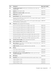
Spare part number Description 686274-001 RTC battery 686275-001 Display Rubber Kit (includes display assembly rubber bumpers) 686276-001 Rubber Feet Kit (includes front and rear rubber feet) 686278-001 Screw Kit ... finish for use on HP 2000 Notebook PC computer models (includes the TouchPad board) 686283-001 Top cover in black licorice finish for use on Compaq Presario CQ58 computer models (includes the TouchPad board) 686284-001 Top cover in winter blue finish for use on HP 2000 Notebook PC computer models (includes the...
Spare part number Description 686274-001 RTC battery 686275-001 Display Rubber Kit (includes display assembly rubber bumpers) 686276-001 Rubber Feet Kit (includes front and rear rubber feet) 686278-001 Screw Kit ... finish for use on HP 2000 Notebook PC computer models (includes the TouchPad board) 686283-001 Top cover in black licorice finish for use on Compaq Presario CQ58 computer models (includes the TouchPad board) 686284-001 Top cover in winter blue finish for use on HP 2000 Notebook PC computer models (includes the...

Maintenance and Service Guide
Page 44
...computer. Service tag When ordering parts or requesting information, provide the computer serial number and model number provided on page 38 for battery removal instructions. There are needed. 36 Chapter 4 Removal and replacement procedures Item (1) (2) (3) Component Product name Serial number ...(s/n) Part number/Product number (p/n) Description This is necessary to remove the battery to the front of each product. It is the product name affixed to obtain these numbers. This number provides specific information ...
...computer. Service tag When ordering parts or requesting information, provide the computer serial number and model number provided on page 38 for battery removal instructions. There are needed. 36 Chapter 4 Removal and replacement procedures Item (1) (2) (3) Component Product name Serial number ...(s/n) Part number/Product number (p/n) Description This is necessary to remove the battery to the front of each product. It is the product name affixed to obtain these numbers. This number provides specific information ...

Maintenance and Service Guide
Page 46
... Turn the computer upside down on the rear edge of the battery with the notches on a flat surface. 2. To insert the battery: 1. Align the tabs on the rear edge of the battery bay. 2. Pivot the front edge of the battery (2) up and back. 4. Before disassembling the computer, follow... 593553-001 IMPORTANT: The customer should not attempt to release the battery. 3. Slide the battery release latch (1) to replace the computer battery, which is seated. (The battery release latch will automatically lock into the battery bay until it is installed and sealed at the factory. If ...
... Turn the computer upside down on the rear edge of the battery with the notches on a flat surface. 2. To insert the battery: 1. Align the tabs on the rear edge of the battery bay. 2. Pivot the front edge of the battery (2) up and back. 4. Before disassembling the computer, follow... 593553-001 IMPORTANT: The customer should not attempt to release the battery. 3. Slide the battery release latch (1) to replace the computer battery, which is seated. (The battery release latch will automatically lock into the battery bay until it is installed and sealed at the factory. If ...

Maintenance and Service Guide
Page 47
... cord from the computer. 3. The memory module/wireless module compartment cover is off the computer. Spread the retaining tabs (1) on page 38). Remove the battery (see Battery on each side of the memory module/wireless module compartment cover (2) up .) Component replacement procedures 39 Disconnect the power from the computer by sliding it...
... cord from the computer. 3. The memory module/wireless module compartment cover is off the computer. Spread the retaining tabs (1) on page 38). Remove the battery (see Battery on each side of the memory module/wireless module compartment cover (2) up .) Component replacement procedures 39 Disconnect the power from the computer by sliding it...

Maintenance and Service Guide
Page 49
... Memory module on page 39). Remove the memory module/wireless module compartment cover (see Battery on the WLAN module. NOTE: The #1 WLAN antenna cable is connected to the WLAN module #1 terminal. 3. Disconnect all external devices from the terminals on page ...
... Memory module on page 39). Remove the memory module/wireless module compartment cover (see Battery on the WLAN module. NOTE: The #1 WLAN antenna cable is connected to the WLAN module #1 terminal. 3. Disconnect all external devices from the terminals on page ...

Maintenance and Service Guide
Page 51
... power from the computer by unplugging the power cord from the computer. 4. Remove the memory module/wireless module compartment cover (see Battery on page 39). If you are unsure whether the computer is off the computer. Component replacement procedures 43 For use in country/...Hibernation, turn the computer on, and then shut it down through the operating system. 2. Disconnect all external devices from the computer. 3. Remove the battery (see Memory module on page 38). 5. Keyboard NOTE: The keyboard spare part kit includes the keyboard cable. Turn off or in the United ...
... power from the computer by unplugging the power cord from the computer. 4. Remove the memory module/wireless module compartment cover (see Battery on page 39). If you are unsure whether the computer is off the computer. Component replacement procedures 43 For use in country/...Hibernation, turn the computer on, and then shut it down through the operating system. 2. Disconnect all external devices from the computer. 3. Remove the battery (see Memory module on page 38). 5. Keyboard NOTE: The keyboard spare part kit includes the keyboard cable. Turn off or in the United ...
Maintenance and Service Guide
Page 55
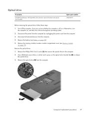
Turn off or in Hibernation, turn the computer on page 39). Remove the battery (see Memory module on , and then shut it down through the operating system. 2. Disconnect all external devices from the computer. Remove the optical drive (3) from ... the optical drive to press on page 38). 5. Component replacement procedures 47 Remove the optical drive: 1. Remove the memory module/wireless module compartment cover (see Battery on the optical drive bracket tab (2) to release the optical drive. 3. If you are unsure whether the computer is off the computer. Use a flat-blade...
Turn off or in Hibernation, turn the computer on page 39). Remove the battery (see Memory module on , and then shut it down through the operating system. 2. Disconnect all external devices from the computer. Remove the optical drive (3) from ... the optical drive to press on page 38). 5. Component replacement procedures 47 Remove the optical drive: 1. Remove the memory module/wireless module compartment cover (see Battery on the optical drive bracket tab (2) to release the optical drive. 3. If you are unsure whether the computer is off the computer. Use a flat-blade...

Maintenance and Service Guide
Page 57
... unsure whether the computer is off the computer. Loosen the captive screw (1) that secures the hard drive compartment cover to the computer. 2. Remove the battery (see Memory module on page 38). 5. Description 750-GB, 5400-rpm, 9.5-mm 640-GB, 5400-rpm, 9.5-mm 500-GB, 5400-rpm, ...669299-001 622643-001 686261-001 Before removing the hard drive, follow these steps: 1. Remove the memory module/wireless module compartment cover (see Battery on page 39). Lift the rear edge of the hard drive compartment cover (2) up and forward until it down through the operating system. ...
... unsure whether the computer is off the computer. Loosen the captive screw (1) that secures the hard drive compartment cover to the computer. 2. Remove the battery (see Memory module on page 38). 5. Description 750-GB, 5400-rpm, 9.5-mm 640-GB, 5400-rpm, 9.5-mm 500-GB, 5400-rpm, ...669299-001 622643-001 686261-001 Before removing the hard drive, follow these steps: 1. Remove the memory module/wireless module compartment cover (see Battery on page 39). Lift the rear edge of the hard drive compartment cover (2) up and forward until it down through the operating system. ...

Maintenance and Service Guide
Page 60
... the computer is off the computer. Remove the RTC battery: 1. Remove the battery (see Battery on , and then shut it down through the operating system. 2. Remove the RTC battery (2). 52 Chapter 4 Removal and replacement procedures Disconnect all external devices from the computer. 3. RTC battery Description RTC battery Spare part number 686274-001 Before removing the RTC...
... the computer is off the computer. Remove the RTC battery: 1. Remove the battery (see Battery on , and then shut it down through the operating system. 2. Remove the RTC battery (2). 52 Chapter 4 Removal and replacement procedures Disconnect all external devices from the computer. 3. RTC battery Description RTC battery Spare part number 686274-001 Before removing the RTC...
Maintenance and Service Guide
Page 61
Description In black licorice finish for use on Compaq Presario CQ58 computer models In black licorice finish for use on HP 2000 ...cover: ● Power button board (see Power button board on page 57) ● TouchPad button board (see Battery on HP 2000 Notebook PC computer models Spare part number 686283-001 686282-001 686284-001 Before removing the top ...these steps: 1. Disconnect the power from the computer by unplugging the power cord from the computer. 4. Remove the battery (see TouchPad button board on page 39) b. Top cover NOTE: The top cover spare part kit includes the ...
Description In black licorice finish for use on Compaq Presario CQ58 computer models In black licorice finish for use on HP 2000 ...cover: ● Power button board (see Power button board on page 57) ● TouchPad button board (see Battery on HP 2000 Notebook PC computer models Spare part number 686283-001 686282-001 686284-001 Before removing the top ...these steps: 1. Disconnect the power from the computer by unplugging the power cord from the computer. 4. Remove the battery (see TouchPad button board on page 39) b. Top cover NOTE: The top cover spare part kit includes the ...

Maintenance and Service Guide
Page 62
Remove the six Phillips PM2.5×6.5 screws (1) and the two Phillips PM2.5×10.0 screws (2) that secure the top cover to the computer. 3. Remove the four Phillips PM2.0×2.5 screws on the front edge of the battery bay and in the hard drive bay that secure the top cover to the computer. 54 Chapter 4 Removal and replacement procedures Remove the top cover: 1. Remove the four Phillips PM2.5×4.0 screws on the rear edge of the battery bay and near the hard drive connector that secure the top cover to the computer. 2.
Remove the six Phillips PM2.5×6.5 screws (1) and the two Phillips PM2.5×10.0 screws (2) that secure the top cover to the computer. 3. Remove the four Phillips PM2.0×2.5 screws on the front edge of the battery bay and in the hard drive bay that secure the top cover to the computer. 54 Chapter 4 Removal and replacement procedures Remove the top cover: 1. Remove the four Phillips PM2.5×4.0 screws on the rear edge of the battery bay and near the hard drive connector that secure the top cover to the computer. 2.

Maintenance and Service Guide
Page 65
Disconnect all external devices from the computer. 3. Remove the battery (see Battery on page 43) c. Keyboard (see Memory module on page 49) d. Component replacement procedures 57 Memory module/wireless module compartment cover (see Keyboard on page 38), ...
Disconnect all external devices from the computer. 3. Remove the battery (see Battery on page 43) c. Keyboard (see Memory module on page 49) d. Component replacement procedures 57 Memory module/wireless module compartment cover (see Keyboard on page 38), ...

Maintenance and Service Guide
Page 66
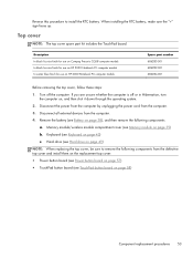
... power button board (2). Disconnect the power from the computer by unplugging the power cord from the computer. 4. Keyboard (see Battery on page 43) c. Disconnect all external devices from the computer. 3. Remove the battery (see Keyboard on page 38), and then remove the following components: a. Memory module/wireless module compartment cover (see Top...
... power button board (2). Disconnect the power from the computer by unplugging the power cord from the computer. 4. Keyboard (see Battery on page 43) c. Disconnect all external devices from the computer. 3. Remove the battery (see Keyboard on page 38), and then remove the following components: a. Memory module/wireless module compartment cover (see Top...

Maintenance and Service Guide
Page 69
... cover (see Memory module on , and then shut it down through the operating system. 2. Top cover (see Battery on page 53) Remove the optical drive connector cable: 1. Component replacement procedures 61 Remove the battery (see Top cover on page 38), and then remove the following components: a. Turn off or in Hibernation, turn...
... cover (see Memory module on , and then shut it down through the operating system. 2. Top cover (see Battery on page 53) Remove the optical drive connector cable: 1. Component replacement procedures 61 Remove the battery (see Top cover on page 38), and then remove the following components: a. Turn off or in Hibernation, turn...


